12
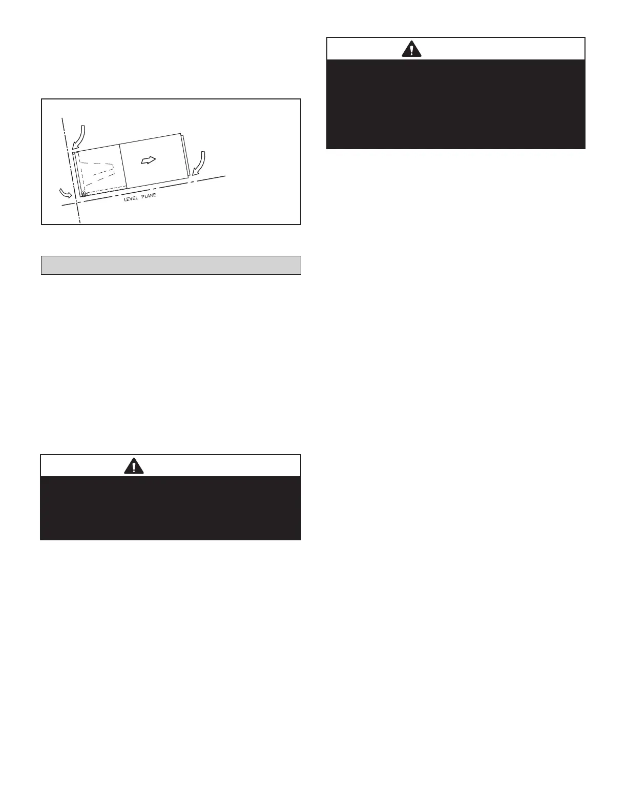
Sloping The Unit
Make sure the unit is sloped (similar to the slope shown in
gure 12) (horizontal or vertical) so that the drain pan will
empty completely without water standing in the pan.
Figure 12. Sloping the Unit
Duct System
Duct system must be designed within the range of external
static pressure the unit is designed to operate against. It is
important that the system airow be adequate. Make sure
supply and return duct, grills, special lters, accessories,
etc. are accounted for in total resistance.
Supply plenum is attached to the 3/4” duct anges supplied
with the unit. Attach anges around the blower outlet.
Secure the supply and return duct to the unit anges,
using proper fasteners for the type of duct used.
The air handler is provided with anges for the connection
of the supply plenum.
Supply and return duct system must be adequately sized
to meet the system's air requirements and static pressure
capabilities. Supply plenum should be the same size as
the anged opening provided around the blower outlet
and should extend at least 3 ft. from the air handler before
turning or branching o plenum into duct runs. The plenum
forms an extension of the blower housing and minimizes
air expansion losses from the blower.
Field installed duct must comply with the National Fire
Protection Association NFPA 90A, NFPA 90B and any
applicable local ordinance.
Installing Duct System
• Connect supply air duct to the ange on top of the air
handler. If an isolation connector is used, it must be
nonammable.
• When sizing the return air lter grille, a minimum
surface area of 200 sq. in. per ton is recommended.
Installation Guidelines
• Install a eld-provided isolation grommet to prevent
transmission of vibration from unit to structural ceiling.
• Provide separate support for the weight of the duct
system. Duct system must not be supported by the
indoor unit.
• Use exible joints (canvas) at the point where the duct
connects to the unit on both ends. Material must meet
all local and national code requirements.
• When unit is being installed in a location where even
the slightest noise would be a problem (meeting room
or other very quiet space), design duct system to
avoid transmission of vibration to the structure to the
extent possible.
THIS CORNER SHOULD BE
5/8” (+/- 1/8”) HIGHER THAN
DRAIN CORNER
DRAIN
CORNER
THIS CORNER SHOULD BE 5/8” (+/- 1/8”)
HIGHER THAN DRAIN CORNER
AIR FLOW
WARNING
Do not, under any circumstances, connect return duct to
any other heat producing device such as replace insert,
stove, etc. Unauthorized use of such of devices may
result in re, carbon monoxide poisoning, explosion,
personal injury or property damage.
IMPORTANT
If an elbow is included in the plenum close to the unit, it
must not be smaller than the dimensions of the supply
duct ange on the unit.
The front glange on the return duct if connected to the
blower casing must not be screwed into the area where
the power wiring is located. Drills or sharp screw points
can damage insulation on wires located inside unit.
 Loading...