Page 13
XC21 SERIES
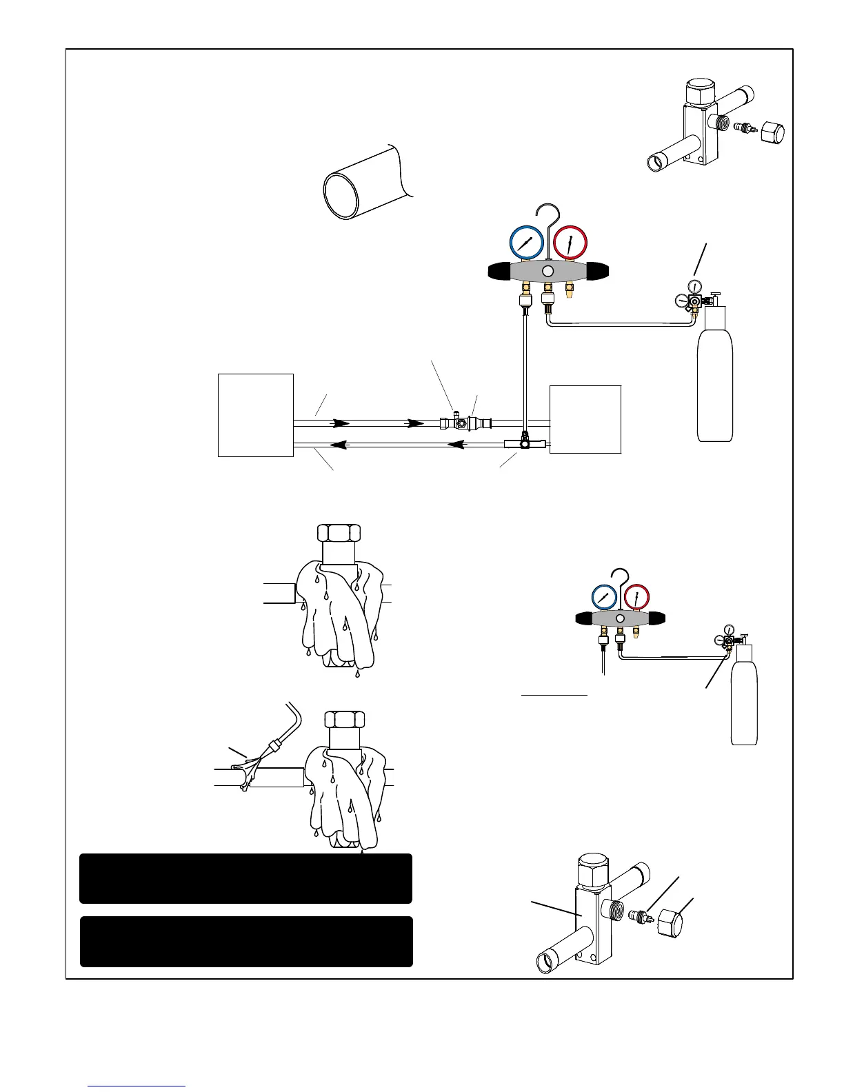
CUT AND DEBUR
CAP AND CORE REMOVAL
Cut ends of the refrigerant lines square
(free from nicks or dents) and debur the
ends. The pipe must remain round and do
not pinch end of the line.
Remove service cap and core
from both the vapor and liquid line
service ports.
ATTACHED GAUGES
OUTDOOR
UNIT
LIQUID LINE
VAPOR LINE
LIQUID LINE SERVICE
VALVE
VAPOR LINE
SERVICE
VALVE
ATTACH
GAUGES
INDOOR
UNIT
SERVICE PORT MUST BE OPEN TO ALLOW EXIT
POINT FOR NITROGEN
A Connect gauge set low pressure side to liquid line service valve.
B Connect gauge set center port to bottle of nitrogen with regulator.
NITROGEN
HIGHLOW
USE REGULATOR TO
FLOW NITROGEN AT 1
TO 2 PSIG.
WRAP SERVICE VALVE
FLOW NITROGEN
To protect components during
brazing, wrap a wet cloth around
the liquid line service valve body
and copper tube stub and use
another wet cloth underneath the
valve body to protect the base
paint.
Flow regulated nitrogen (at 1 to 2 psig) through the refrigeration
gauge set into the valve stem port connection on the liquid line service
valve and out of the valve stem port connection on the vapor service
valve.
NOTE The fixed orifice or check
expansion valve metering device at the
indoor unit will allow low pressure
nitrogen to flow through the system.
NITROGEN
HIGH
LOW
USE REGULATOR TO
FLOW NITROGEN AT 1
TO 2 PSIG.
BRAZE LINE SET
INSTALL SERVICE PORT CAPS ONLY
Braze the liquid line to the liquid line
service valve. Turn off nitrogen flow.
After all connections have been brazed, disconnect manifold gauge
set from service ports, cool down piping with wet rag and remove all
wrappings. Do not reinstall cores until after evacuation procedure.
Reinstall service port caps if desired to close off refrigerant ports.
IMPORTANT Connect gauge set low pressure side to vapor
line service valve and repeat procedure starting at paragraph 4
for brazing the liquid line to service port valve.
SERVICE PORT CORE
SERVICE PORT CAP
SERVICE PORT
WARNING Allow braze joint to cool before removing the wet
rag from the service valve. (TEMPERATURES ABOVE 250ºF
CAN DAMAGE VALVE SEALS
CONNECTIONS
BRAZING
1
2
3
4
5
6
7
B
A
POINT FLAME AWAY FROM
SERVICE VALVE
NOTE − Use silver alloy brazing rods with five or six percent minimum silver
alloy for copper−to−copper brazing, 45 percent alloy for copper−to−brass and
copper−to−steel brazing.