Page 23
XC21 SERIES
Field Control Wiring
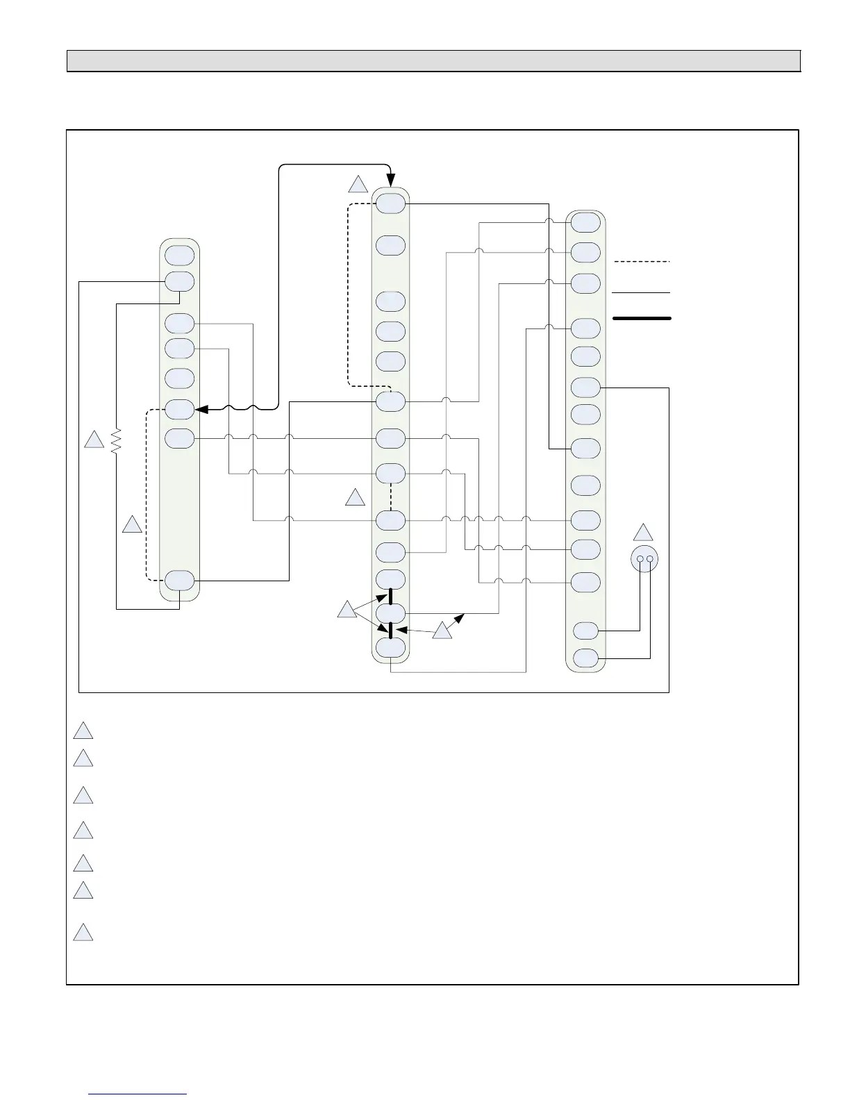
The following two illustrations provide examples on how to install control wiring using a non−communicating thermostat. For
examples of how to install control wiring in complete or partial communicating systems, see the icomfort Toucht thermostat
Quick Start Guide which is provided with the thermostat.
Y1
O
R
W1
G
D
R
Y1
L
C
C
B
Y2
Y2
W
O
DS
L
T
T
W2
H
W3
H
O
C
L
Y2
DS
DH
G
R
Y1
W2
W1
R connection required for air conditioners with compressor diagnostic function. Resistor Kit (Cat# 47W97) is required when using the
ComfortSense 7000 (Y0349) with Air Conditioner compressor diagnostic feature. Resistor kit not required when using ComfortSense 7000
(Y2081).
Outdoor sensor for outdoor temperature display (Optional).
Cut on−board link (clippable wire) from Y1−Y2 2 STAGE COMPR for two−stage compressor and two−speed fan operation.
1
2
3
5
6
1
2
5
6
7
ComfortSense[ 7000 Thermostats
Catalog # Y0349 or Y2081
On−board link
Low voltage thermostat
wiring
Flat metal jumper
4
3
4
A175 main control comes from factory with metal jumpers across W1, W2 and W3. For one−stage electric heat, do not remove
metal jumpers.
A175 main control comes from factory with metal jumpers across W1, W2 and W3. For two−stage electric heat, remove metal
jumper between W1 to W2 and connect thermostat wire between Air Handler Control W2 to thermostat W2.
7
Cut loop jumper (clippable wire)
for Humiditrol
®
application. This will slow the outdoor unit’s blower motor to
250 rpm. A wire must be installed between the DS terminals on the air handler and outdoor unit controls.
Cut on−board link (clippable wire)
DS − R for Humiditrol
®
or Harmony III
TM
applications. This will slow the indoor blower motor to
the lowest speed. See air handler installation instruction or engineering handbook for lowest fan speed.
Air Handler
XC21 Two−Stage
Air Conditioner A175 Control
Figure 9. ComfortSense® 7000 Series Thermostat Non−Communicating Connections −
Air Hander/Two−Stage Air Conditioner