Page 43
XC21 SERIES
2. Verify LED RPM indicator is displaying the correct
flash sequence for the applicable size unit (see table
table 16).
3. Test DC voltage output on the A177 fan motor control’s
J2 terminals (see figure 24) while under full load and
verify the voltage read to the voltage listed in table 16
for the applicable size unit.
4. If no voltage is detected at the J2 terminals, verify
there is a Y1 demand at the thermostat and applicable
voltages detected all A177 fan motor control voltage
inputs, see table 12. NOTE: Voltage will be present at
specific inputs depending on the type of demand (low
or high stage and EDA operation).
5. If there is a demand, proceed to the next section for
further testing.
VERIFYING CORRECT INPUT VOLTAGE (ECM/Y1,
ECM/Y2, ECM C AND EXT ECM/R)
Using a volt meter, check voltages on the following A177
fan motor control inputs using table 12. Voltage will only be
present during a thermostat demand. See figure 25 for test
example.
If correct voltage is present at A177 fan motor control
inputs and no voltage or incorrect voltages are present at
J2 output, replace A177 fan motor control.
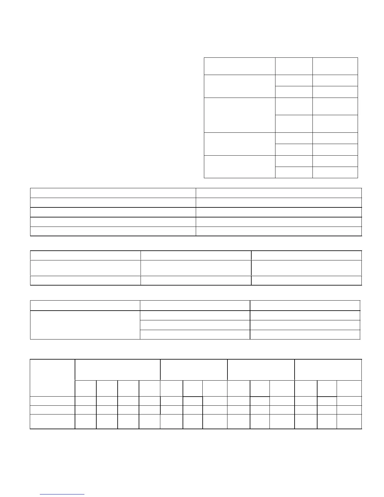
Table 12. A177 Fan Motor Control Voltage Inputs
Input
Thermostat
Demand
Voltage
Present
ECM/Y1 and ECM C
(Low Stage)
YES 24VDC
NO NONE
ECM/Y1 − ECM/Y2 and
ECM C
(High Stage)
YES
24VDC at each
input
NO
NONE at each
input
ECM/Y2 and ECM C
(EDA Operation)
YES 24VDC
NO NONE
EXT ECM/R and ECM C
YES 24VAC
NO NONE
Table 13. A177 Fan Motor Control Flash and Pause Durations
Flash or Pause State Duration
Flash Flash Three flashes per second
Slow Flash One flash per second
Short Pause Two seconds of OFF time.
Long Pause Five seconds of OFF time.
Table 14. A177 Fan Motor Control Error/Fault LED Codes
Unit Status A177 Fan Motor Control LED Possible Cause
Mismatched RPM Fast Flash with no pause
Internal feedback, PWM does not match tar-
get.
CRC Failure Constant ON. Microcontroller CRC failure.
Table 15. A177 Fan Motor Control Stage Operation LED Indicator Codes
Unit Status Unit Status A177 Fan Motor Control LED
Two Stage Operation
Low Stage ECM1/Y1 ONLY One slow flash, then short pause.
High Stage ECM1/Y1 and ECM2/Y2 Two slow flash, then short pause.
EDA Operation ECM2/Y2 ONLY Three slow flash, then short pause.
Table 16. Two Stage A177 Fan Motor Control RPM Jumper Settings, LED RPM Indicator and
P2 DC Voltage Outputs
Application
CFM Profile Pin Select
Low Stage ECM1/Y1
Only
High Stage ECM1/Y1
and ECM2/Y2
EDA Operation
ECM2/Y2 Only
4 3 2 1 RPM
LED
Code
DC Volt RPM
LED
Code
DC Volt RPM
LED
Code
DC Volt
XC21−024 ON ON OFF OFF 475 6 15.1 550 8 17.6 200 3 6.3
XC−036 ON OFF ON ON 525 7 16.8 600 8 19.2 225 3 7.0
XC21−048 and
XC21−060
ON OFF OFF ON 600 8 19.2 675 9 21.6 225 3 7.0
* LED Code indicates A177 Fan Motor Control LED flash sequence. For example, LED Code 9 indicates 9 slow flashes and pause.