Page 34
System Operation- (XP14-XXX-230-01
through 07)
The demand defrost controller measures differential
temperatures to detect when the system is performing
poorly because of ice build-up on the outdoor coil. The
controller self-calibrates when the defrost system starts
and after each system defrost cycle. The defrost control
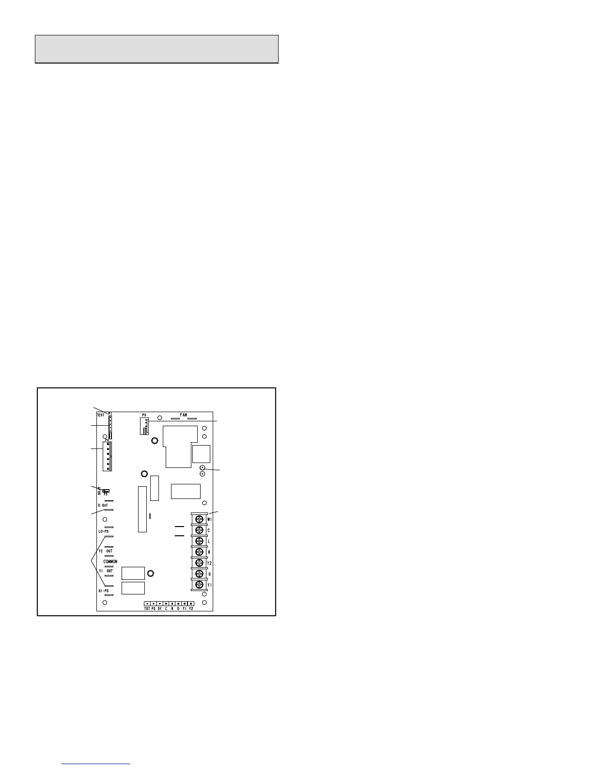
board components are shown in figure 19.
The control monitors ambient temperature, outdoor coil
temperature, and total run time to determine when a
defrost cycle is required. The coil temperature probe is
designed with a spring clip to allow mounting to the outside
coil tubing. The location of the coil sensor is important for
proper defrost operation.
NOTE - The demand defrost board accurately measures
the performance of the system as frost accumulates on the
outdoor coil. This typically will translate into longer running
time between defrost cycles as more frost accumulates on
the outdoor coil before the board initiates defrost cycles.
FILTER DRIER
The unit is equipped with a large-capacity bi-flow filter drier
which keeps the system clean and dry. If replacement is
necessary, order another of the same design and capacity.
The replacement filter drier must be suitable for use with
HFC-410A refrigerant.
DEFROST CONTROL BOARD
Figure 19 provides a basic illustration of the layout of the
defrost control board. Table 10 provides information
concerning pin-out and jumper configurations.
24V TERMINAL
STRIP
CONNECTIONS
DIAGNOSTIC
LEDS
PRESSURE
SWITCH
CIRCUIT
CONNECTIONS
TEST PINS
Note - Component Locations Vary by Board Manufacturer.
SENSOR PLUG IN
(COIL, AMBIENT,
& DISCHARGE
SENSORS)
Figure 19. Defrost Control Board
REVERSING
VALVE
DELAY
PINS
LOW
AMBIENT
THERMOSTAT
PINS
DEFROST
TERMINATION
PIN SETTINGS
Test: Defrost Temperature Termination Shunt
(Jumper) Pins—The defrost board selections are: 50, 70,
90, and 100°F (10, 21, 32 and 38°C). The shunt
termination pin is factory set at 50°F (10°C). If the
temperature shunt is not installed, the default termination
temperature is 90°F (32°C).
Note: The Y1 input must be active (ON) and the “O” room
thermostat terminal into board must be inactive.
DIAGNOSTIC LEDS
The state (Off, On, Flashing) of two LEDs on the defrost
board (DS1 [Red] and DS2 [Green]) indicate diagnostics
conditions that are described in table 13.
DELAY MODE
The defrost board has a field-selectable function to reduce
occasional sounds that may occur while the unit is cycling
in and out of the defrost mode. When a jumper is installed
on the DELAY pins, the compressor will be cycled off for 30
seconds going in and out of the defrost mode. Units are
shipped with jumper installed on DELAY pins.
DEFROST BOARD PRESSURE SWITCH
CONNECTIONS
The unit's automatic reset pressure switches (LO PS - S87
and HI PS - S4) are factory-wired into the defrost board on
the LO-PS and HI-PS terminals, respectively.
Low Pressure Switch (LO-PS)
When the low pressure switch trips, the defrost board will
cycle off the compressor, and the strike counter in the
board will count one strike. Low Pressure (auto reset) -
trip at 25 psig; reset at 40 psig. The low pressure switch is
ignored under the following conditions:
during the defrost cycle and 90 seconds after the
termination of defrost
when the average ambient sensor temperature is below
15° F (-9°C)
for 90 seconds following the start up of the compressor
during test mode
High Pressure Switch (HI-PS)
When the high pressure switch trips, the defrost board will
cycle off the compressor, and the strike counter in the
board will count one strike. High Pressure (auto reset) -
trip at 590 psig; reset at 418 psig.
Low Ambient Thermostat Pins - P3 provides selection of
the Y2 compressor lock-in temperature. The XP14 series
heat pumps do not use a Y2 compressor and therefore
these pins are not active.
FIVE-STRIKE LOCKOUT FEATURE
The internal control logic of the board counts the pressure
switch trips only while the Y1 (Input) line is active. If a
pressure switch opens and closes four times during a Y1
(Input), the control logic will reset the pressure switch trip
counter to zero at the end of the Y1 (Input). If the pressure
switch opens for a fifth time during the current Y1 (Input),
the control will enter a lockout condition.
The five-strike pressure switch lockout condition can be
reset by cycling OFF the 24-volt power to the control board
or by shorting the TEST pins between 1 and 2 seconds. All
timer functions (run times) will also be reset.
If a pressure switch opens while the Y1 Out line is
engaged, a 5-minute short cycle will occur after the switch
closes.
 Loading...