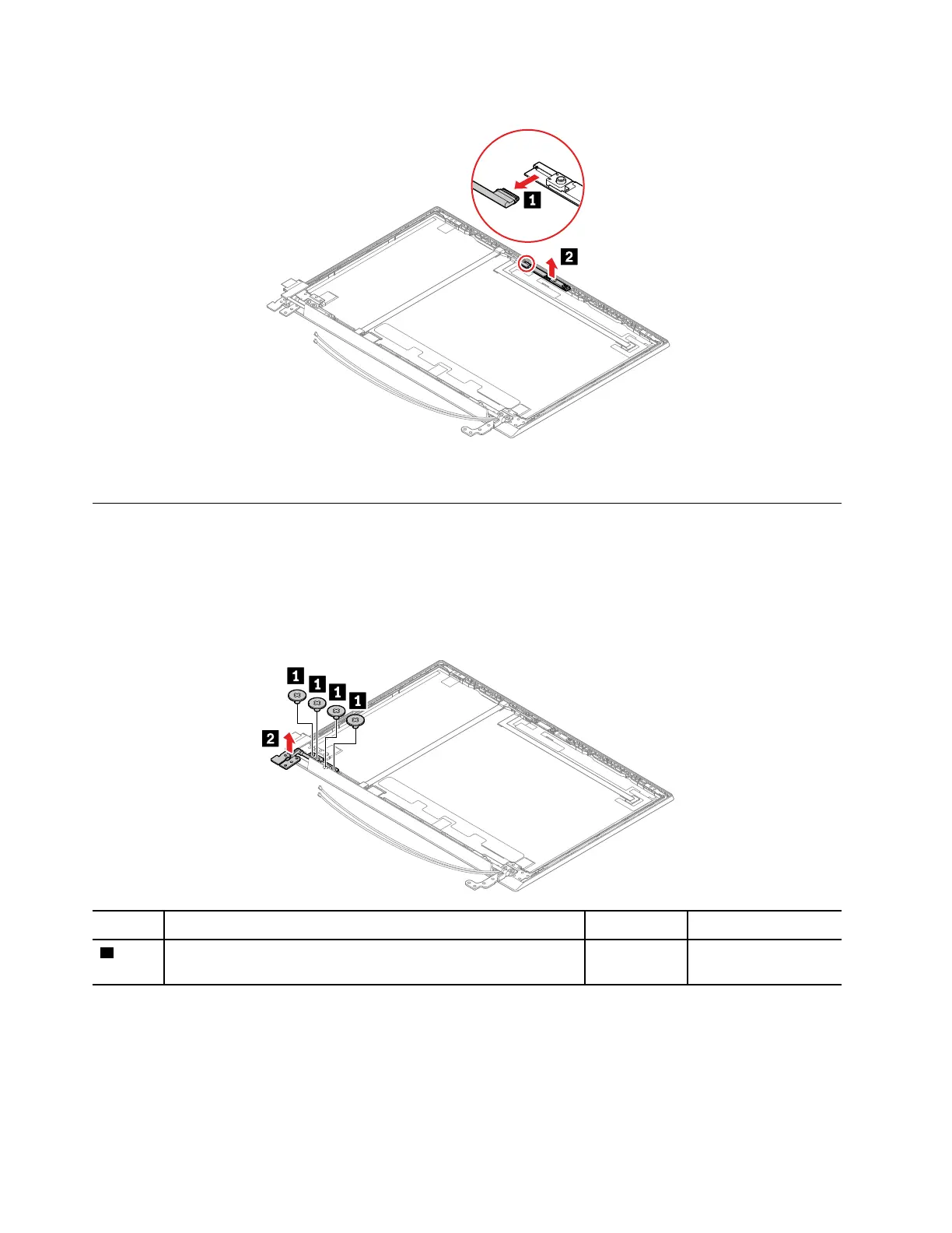
Removal steps of the camera/microphone module
When installing: Ensure that the connector is attached firmly.
2050 LCD cable
For access, remove these FRUs in order:
• “1160 LCD unit” on page 81
• “2010 LCD bezel ” on page 83
• “2020 LCD panel” on page 84
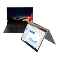
Removal steps of the LCD cable
Step Screw (quantity) Color Torque
1
M2 × 3 mm, wafer-head, nylon-coated (4) Black 0.181 Nm
(1.85 kgf-cm)
86 E590, R590, and E595 Hardware Maintenance Manual



 To Next Page