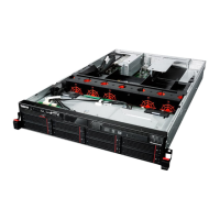
2.Ensurethatallinternalcablesareconnectedandroutedcorrectlyandsecuredbyanycableclipsor
tiesintheserver.Keepcablesclearofthehingesandsidesofthechassistoavoidinterferencewith
reinstallingthecoolingshroudandtheservercover.Thefollowingillustrationshowsanexampleofthe
cableroutinginthechassiswithtwobackplanesfor162.5-inchharddiskdrives.
•Routethesignalcables
1throughtheleftinnersideofthechassis.Thesignalcablesincludethe
mini-SAStomini-SASsignalcables,thefrontpanelcable,thefrontpanelUSBcable,thediagnostic
modulecable,theSATAsignalcablefortheopticaldriveifyourserverhasaslimopticaldrive
installed,andthecableforthefrontVGADB-15connector.
•IfyourserverhasaRAIDcardandanexpandercardinstalled,properlyroutethemini-SASto
mini-SASsignalcables
2thatareconnectedfromtheRAIDcardtotheexpandercard.
•Routethebackplanepowercables3throughtherightinnersideofthechassis.
•Ifyourserverhasaslimopticaldriveinstalled,connectthepowercable4fortheopticaldrivetothe
opticaldrivepowerconnectoronthebackplaneandproperlyroutethecableinthechassis.
Figure131.Cablerouting
3.Ifyouhaveremovedthecoolingshroud,reinstallit.See“Removingandreinstallingthecoolingshroud”
onpage78.
4.Forservermodelswith2.5-inchhot-swapharddiskdrives,ifyouhaveremovedthefrontbezel,reinstall
it.See“Removingandreinstallingthefrontbezel”onpage75.
Chapter6.Installing,removing,orreplacinghardware163
 Loading...