Electrical installation
EMC-compliant installation
Installation of a CE-typical drive system
5
56
EDB712 DE/EN 2.1
3
1 20
4xx_012
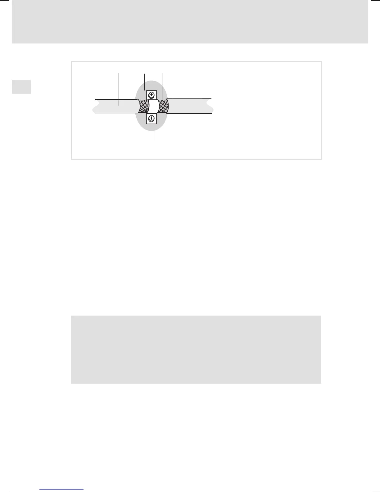
Fig. 2 Large area shield connection
Shielded cable
Bare metal mounting areas
Braid
Earthing clamp
ƒ When laying cables, lay motor cable separately from signal and mains
cables.
ƒ Connect the mains input and motor output to separate terminal strips.
ƒ Lay the cables as close as possible to the reference potential. Suspended
cables act like antennas.
If you use the drive systems with drive controllers in residential areas:
ƒ Check for compliance with the conducted interference levels in
accordance with EN 55022 class B on the supply side in the building.
ƒ Check for permissible interference radiation in accordance with
EN 55022 class B at the boundaries of the building.
Note!
Devices operated close to the drive controller that are not immune
to interference in accordance with EN 55022 class B may be
electromagnetically affected by the drive controller.
Only operate devices immune to interference in accordance with EN
55022 class B near the drive controller.