Electrical installation
Connection plan
Connection of control signals to the drive controller 712
5
61
EDB712 DE/EN 2.1
5.3.3 Connection of control signals to the drive controller 712
A
S
7891213141617
=
+
-
7
8
E
10K/1Wlin.
A
S
E
10K
RFR
+
++
Controller
enable
Setpoint
potentiometer
Master voltage
U = 10 V
LN
Dancer
712_005
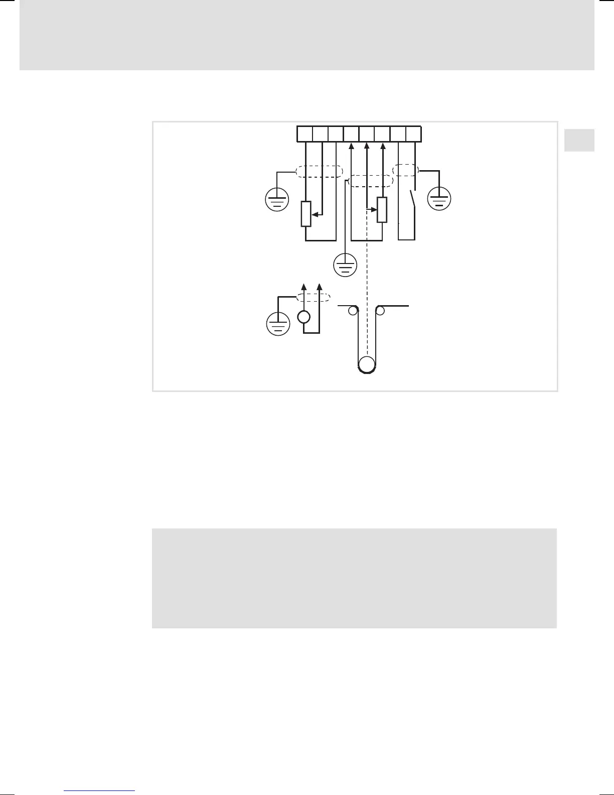
Fig. 7 Connection of setpoint signals and the controller enable
ƒ The device can evaluate a setpoint signal from a potentiometer or master
voltage using terminals 7, 8 and 9. In addition, for winding applications a
second setpoint can be defined at terminals 12, 13 and 14 using a d ancer
potentiometer.
ƒ The drive controller is enabled using an external contact to be connected
to terminals 16 and 17. For this purpose a low current contact (10 V,
10mA)istobeused.
Note!
Use suitable relay contacts if control signals are switched using a
relay.
The drive controller is enabled with switch RFR closed.
If RFR is opened, the enable pulse and the drive controller are reset.