J
22 Technical description 8100_A
4.3.2 OPENINGTHE COVER
To connect the PTC connecting cables, it may be necessary to remove the cover. For
this proceed as folIows:
-
Disconnect mains voltage and wait at least 30s.
Remove control and power terminals
Carefully remove the cover, by inserting a screwdriver into the short slots at
the top side of the inverter.
-
-
4.4
PULSE TRAIN INPUT/INCREMENTAL ENCODER INPUT X5
The 9-pole Sub-D connector X5 serves as digital frequency input and incremental
encoder input, where two complementary signals shifted by 900 are provided. When
using HTLencoders, it is sufficient to provice signals A and B. The inputs A\ and B\
must then be bridged with + Vcc.
The maximum input frequency is 300 kHz for TTL encoders and 100 kHz'for HTL
encoders.
X5: Pin Name
Input/output
Input
Input
Input
Output
Input
Input
Output
Input
Explanation
1
2
3
4
5
6
7
8
9
B
A\
A
+VCC
GND
0\
o
8V2
B\
2nd pulse train/incremental encoder signal
1st pulse train/incremental encoder signal (invertedl
1st pulse train/incremental encoder signal
Supply voltage term. VE9
Controller reference point term. 60
single-track pulse train signal when C005
=16 (inverted)
single-track pulse train signal when C005 = 16
not used
2nd pulse train/incremental encoder signal (inverted)
For the connection of a signal cable via terminals, a suitable adapter
(part no. 348 922) can be supplied.
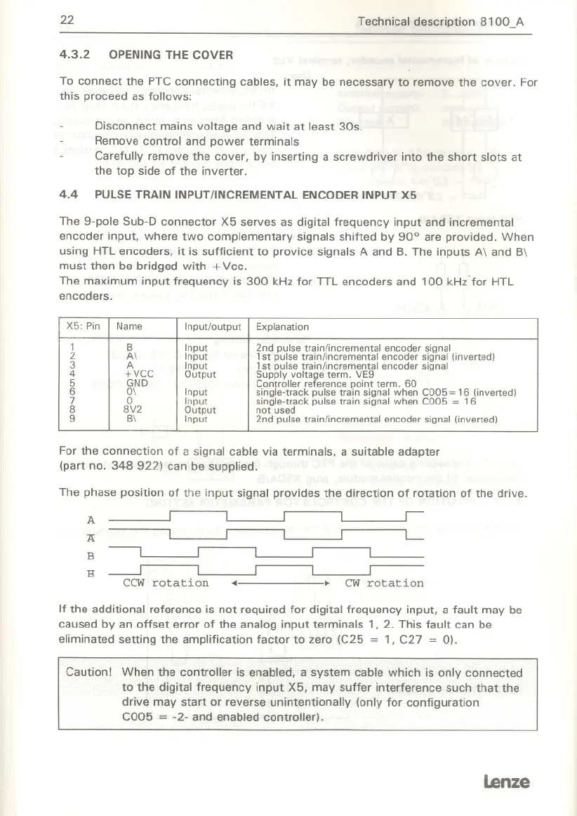
The phase position of the input signal provides the direction of rotation of the drive.
If the additional reference is not required for digital frequency input, a fault may be
caused by an offset error of the analog input terminals 1, 2. This fault can be
eliminated setting the amplification factor to zero (C25 = 1, C27 = 0).
Caution! When the controller is enabled, a system cable which is only connected
to the digital frequency input X5, may suffer interference such that the
drive may start or reverse unintentionally (only for configuration
C005
= -2- and enabled controller).
lenze
A
I I I I
r-
Ä
I
I I I
L-
B
----, I I
I
I
B
---.J
I I I r
CCW rotation
...
CW rotation