Free connection of digital signals
Free configuration of digital input signals
10
Function library
10.13
10.13.1
L
10.13-5
EDS82EV903-1.0-11/2002
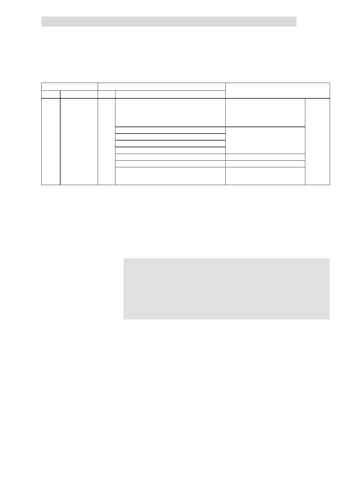
Code IMPORTANTPossible settings
No. SelectionLenzeName
C0411
v
Level inversion of
digital inputs
0
0 Level inversion is switched off • By entering the sum of the selected
values you can invert several inputs
• C0114 and C0411 are identical
• The function ”Parameter set
changeover” cannot be inverted!
1 E1 inverted
2 E2 inverted
4 E3 inverted
8 E4 inverted
16 E5 inverted only application I/O
32 E6 inverted only application I/O
64 T1/T2 inverted T1/T2 can only be connected to
potential-free switches.
T1/T2 is active, if the s witch is open.
The internal digital signals arelinked withan externalsignal sourceby entering the
selection figure of the external signal in the corresponding subcode of C0410.
C0410 can be different for the parameter sets.
l C0410/10 = 2 ð Terminal X3/E2 is the signal source for controller inhibit
(CINH)
l C0410/15 = 32 ð CAN-IN1/word1, Bit 3 is the signal source for the DC
injection brake (DCB)
)
))
) Note!
The process data input words CAN-IN1.W1, CAN-IN1.W2,
CAN-IN2.W1 and CAN-IN2.W2 can be defined as analog word or
as digital word (16 bit). If you link internal digital signals (C0410/x
= 30 ... 105), they must be defined as digital input words.
Otherwise the controller would interpret the bit control information
incorrectly.
l Terminals (X3/E1 ... X3/E6):
– HIGH = +12 V ... +30 V
– LOW = 0 V ... +3 V
l Process data input words:
– HIGH = bit logic 1
– LOW = bit logic 0
l Response times: 1.5 ... 2.5 ms
Signal linkage
Examples
Signal level