Electrical installation 3
EDK94AYFLF DE/EN/FR/ES/IT 1.2
19
H1_E_INST-Belegung_SubD_X10
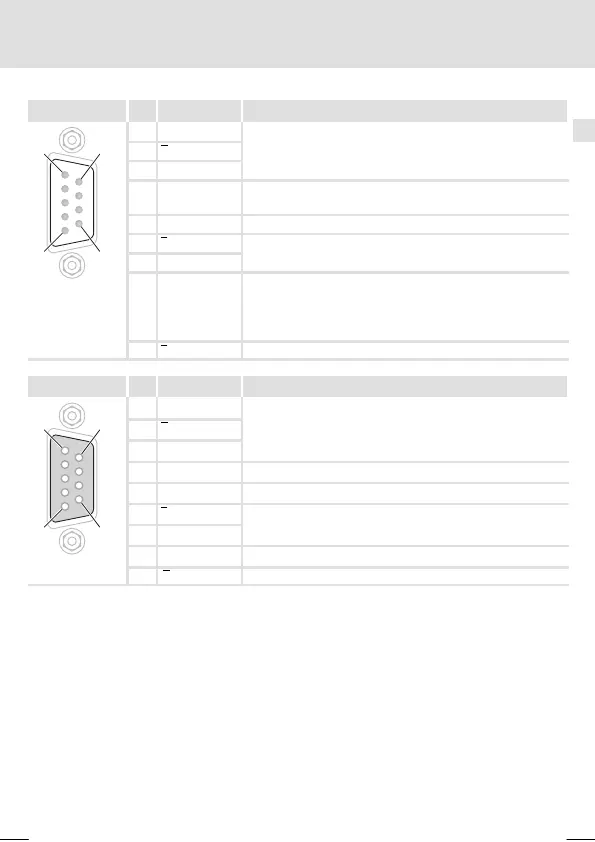
X9 Pin Designation Explanation
1
6
5
9
1 B
TTL input signal from encoder or encoder simulation
2 A
3 A
4 +5 V Regulated voltage supply for encoder
(pin 8 = sense has to be used)
5 GND -
6 Z
TTL input signal from encoder or encoder simulation
7 Z
8
The function of this lead has to be set in the standard device:
z S
z Lc
z E
z Sense (sensor lead for voltage regulation, Lenze setting)
z Lamp control
z Enable
SUBD09010
9 B TTL input signal from encoder or encoder simulation
X10 Pin Designation Explanation
16
59
1 B
TTL output signal from encoder or encoder simulation
2 A
3 A
4 +5 V V
CC
±6 %
5 GND -
6 Z
TTL output signal from encoder or encoder simulation
7 Z
8 Enable Digital outpu t signal
SUBD09010
9 B TTL output signal from encoder or encoder simulation