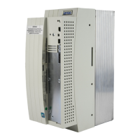
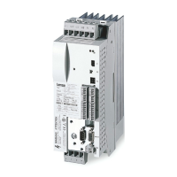
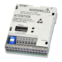
Do you have a question about the Lenze EMF2180IB and is the answer not in the manual?
Records changes and updates to the documentation over different versions.
Explains the notation and symbols used throughout the manual for clarity.
Defines key terms and acronyms used in the communication module manual.
Explains signal words and symbols for safety instructions and application notes.
Provides fundamental safety guidelines and application notes for Lenze components.
Details safety measures specific to the communication module and its application.
Identifies potential risks and hazards remaining after safety measures are applied.
Describes the intended use and purpose of the communication module.
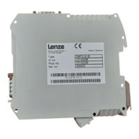
Explains how to identify the module using its nameplate and device designation.
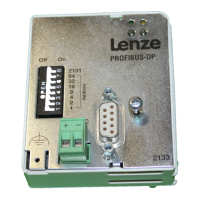
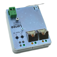
Details the physical connections and interfaces available on the module.
Lists general specifications, operating ranges, and environmental conditions.
Describes the types of electrical insulation applied to module connections.
Provides the physical dimensions and mounting information for the module.
Covers the physical mounting and dismounting of the communication module.
Details wiring, connections for CAN and Ethernet, and voltage supply.
Guides users through the configuration process using Lenze's System bus configurator.
Explains how to configure the module using its integrated web server interface.
Outlines essential checks and configurations before powering up the module.
Describes the LED signaling sequences during the module's initial startup.
Explains how to access and manage parameters within Lenze inverters.
Details the process of transferring data using the CAN bus protocol.
Describes data communication methods over the Ethernet network.
Provides troubleshooting information for common errors and their solutions.
Explains the meaning of LED indicators for CAN bus status and communication.
Details the LED indicators related to Ethernet connection and activity status.
| Brand | Lenze |
|---|---|
| Model | EMF2180IB |
| Category | Control Unit |
| Language | English |

