Do you have a question about the Lenze EMF2181IB and is the answer not in the manual?
Records changes and updates made to the manual over time.
Feedback channel for users to suggest improvements to the documentation.
Details compliance with directives, manufacturer info, and application as directed.
Essential safety measures to prevent personal injury and material damage.
Specific safety guidelines for the communication module and its application context.
Identifies potential dangers like electrostatic discharge and contact protection.
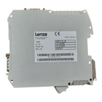
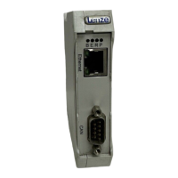
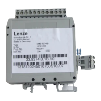
Details the physical components, connectors, and indicators on the communication module.
Explains the meaning of different LED indications on the module for operational status.
Information on how to identify the product, including type code and versions.
Provides specifications like order designation, communication media, baud rates, and environmental conditions.
Details the type of electrical insulation for different connections according to EN 61800-5-1.
Provides the physical dimensions of the communication module.
Instructions for physically mounting and dismounting the module onto a DIN rail.
General guidelines for electrical connections and wiring of the module.
Guidelines for wiring the module to meet EMC requirements for CE compliance.
Steps for establishing communication using the CAN bus.
Steps for establishing communication via the diagnostic interface of the 9400 inverter.
Details terminal data and handling for connecting the module's power supply.
Information on connecting the CAN bus, including connector pin assignments and cable specifications.
Details the pin assignments for connecting an external modem via the RS232 interface.
Describes the telephone socket assignment and the types of connecting cables used.
Pin assignments for the diagnostic interface connector.
Critical checks and initial setup steps before powering on the device.
Steps for commissioning using the system bus configurator software, including requirements.
Detailed steps for configuring the communication module via the system bus configurator.
Initial power-on procedure and LED signalling for the communication module.
Explains how data is transferred using the CAN bus and the module's role.
Describes data transfer capabilities using the diagnostic interface of 9400 series inverters.
Explains how data transfer is performed using the modem via PPP protocol.
Introduces Lenze codes and CANopen objects, defining conventions for indices and codes.
Details specific Lenze codes used for CAN communication and their functions.
Details specific CANopen objects like Device type, Error register, and heartbeat time.
Explains general Lenze codes related to device commands, software version, and status words.
Details codes specific to modem configuration and control.
Explains the meaning of LED signals for the CANopen RUN and ERROR LEDs.
Details the error and status indications for the CANopen RUN and ERROR LEDs in CAN operating mode.
Interprets LED signals for the diagnostic interface operating mode, including error conditions.
Lists various modem standards supported for data transfer, error correction, and compression.
Information on country-specific configurations and approvals for modem usage.
Details AT commands for controlling modem operating modes, modulation, and data compression.
| Brand | Lenze |
|---|---|
| Model | EMF2181IB |
| Category | Control Unit |
| Language | English |
