6 Commissioning
6.4 Initial switch-on
44
Lenze · EMF2180IB communication module (EthernetCAN) · Communication Manual · DMS 5.1 EN · 09/2016 · TD17
_ _ _ _ _ _ _ _ _ _ _ _ _ _ _ _ _ _ _ _ _ _ _ _ _ _ _ _ _ _ _ _ _ _ _ _ _ _ _ _ _ _ _ _ _ _ _ _ _ _ _ _ _ _ _ _ _ _ _ _ _ _ _ _
6.4 Initial switch-on
6.4.1 Signalling sequence of the LEDs
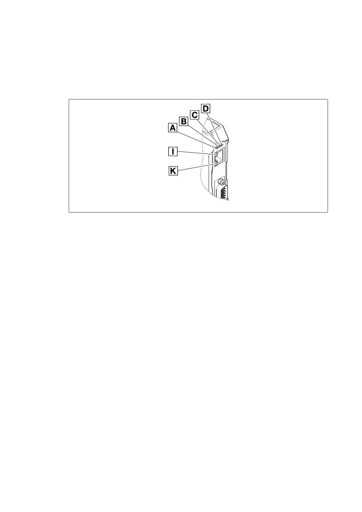
[6-1] LEDs on the front of the communication module
Signalling sequence after switch-on:
1. Initialisation phase of peripherals starts:
•LED D (voltage supply, green) is lit.
2. After the CAN controller initialisation:
•LED C (RUN-LED, green) is blinking.
3. Ethernet connection is established:
•LED I is lit.
•LED A shows the baud rate of the Ethernet connection (10 Mbps or 100Mbps).
•When LED A is blinking, the communication module is currently determining the IP address.
Communication via Ethernet is only possible when this process has been completed.
The device is ready for operation now.
2181FEW001H