EasyManua.ls Logo

Lenze E82ZAFIC010 User Manual

Lenze E82ZAFIC010
31 pages
To Next Page IconTo Next Page
Page #1 background imageLoading...
Page #1 background image
EDK82ZAFIC−010 DE/EN/FR 4.036
legende_kopfzeile−DUMMY_NUM_Reset
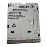
Legend for fold−out page
Pos. Description Detailed
information
Status of the INTERBUS communication (yellow)
66
Connection status to the drive controller (green)
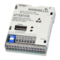
DIP switch S1
l Setting for the last node = OFF
l Setting for all other nodes = ON
64
DIP switches S2 ... S4
l Configuration of
the process data words (PCD)
the parameter data words (PCP)
the ID code
63
Plug connector X3.1
l Connection for external voltage supply of the function module
48
Plug connector X3.2
l Reference terminal GND1, e.g. for external voltage supply of the function
module
l Reference terminal GND2, e.g. for external supply of the controller inhibit
(CINH)
Plug connector X3.3
l Connection for
INTERBUS
controller inhibit (CINH)
internal supply of the controller inhibit (CINH)
Nameplate 45
0Fig. 0Tab. 0
Question and Answer IconNeed help?

Do you have a question about the Lenze E82ZAFIC010 and is the answer not in the manual?

Lenze E82ZAFIC010 Specifications

General IconGeneral
Part NumberE82ZAFIC010
Product Series8200 vector
Input Voltage24 V DC
Communication InterfaceCANopen
Protection ClassIP20
Operating Temperature0°C to +55°C

Summary

Safety instructions

Technical data

General Data

Provides general technical specifications for the function module, including communication and network details.

Connection terminals

Lists and describes the function and level of each terminal on the function module.

Electrical installation

Terminal assignment

Provides a detailed table of terminal assignments, designations, and their functions/levels.

Commissioning

Commissioning steps

A step-by-step guide for configuring and commissioning the function module with the control system.

Control system configuration

Details how to configure the master control system for communication via the function module.

Diagnostics

LED status displays

Explains the meaning of the LED indicators on the function module for diagnostics.

Related product manuals