Do you have a question about the Lenze E84DGFCG Series and is the answer not in the manual?
Details the version changes and updates made to the documentation over time.
Explains the formatting and symbols used in the documentation for clarity.
Provides definitions for key terms and acronyms used throughout the manual.
Describes the signal words and symbols used to indicate important information and dangers.
Provides essential safety measures and general guidelines for using Lenze components.
Outlines safety measures specific to the device and its intended applications.
Identifies potential hazards that may remain even after safety measures are implemented.
Specifies the intended use and operational context for the EtherNet/IP Communication Unit.
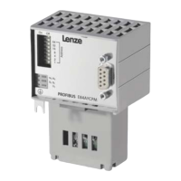
Details the available versions, characteristics, and capabilities of the EtherNet/IP Communication Unit.
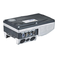
Describes the physical connectors and interfaces available on the Communication Unit.
Lists general specifications, ambient conditions, and operational parameters.
Details the data formats and parameters specific to the communication protocols used.
Explains the timing aspects of data exchange within the EtherNet/IP network.
Describes the delays introduced by the integrated 2-port switch in the Communication Unit.
Provides instructions and diagrams for the physical mounting of the components.
Covers wiring, connections, and electrical setup for the system.
Details the essential checks and preparations required before initial power-up.
Guides the user through setting up the master device (scanner) for EtherNet/IP communication.
Explains how to assign IP addresses and network parameters to the drive.
Describes the process of creating a network connection for device configuration and monitoring.
Provides final steps and considerations for powering up the system for the first time.
Explains the different channels used for transmitting I/O and parameter data.
Describes the implicit and explicit message types used for data exchange.
Illustrates the operational states and transitions of the EtherNet/IP device.
Details how to map and configure input/output data for communication.
Explains how I/O data is assigned to specific ports and channels.
Describes pre-defined technology applications and drive profiles for specific functions.
Explains the structure and use of assembly objects for I/O data exchange.
Guides on configuring I/O data using Lenze's engineering software.
Provides instructions for configuring I/O using Rockwell's RSLogix 5000 software.
Details the process of saving the configured I/O settings.
Explains how to write parameter values to the drive using explicit messages.
Describes how to read parameter values from the drive using explicit messages.
Details how to monitor and react to communication faults in EtherNet/IP.
Explains the meaning of the status LEDs on the Communication Unit.
Describes how to use the engineering software for diagnostic information.
Provides a summary of common EtherNet/IP error codes and their meanings.
Lists and explains error codes specific to the Common Industrial Protocol (CIP).
Correlates Lenze-specific errors with standard DRIVECOM error codes.
Lists and describes all configurable parameters for the Communication Unit.
Provides a reference table for communication attributes and their meanings.
Details standard CIP objects like Identity, Message Router, Assembly, and Connection Manager.
Describes EtherNet/IP specific objects like DLR, QoS, TCP/IP Interface, and Ethernet Link.
Explains objects related to the AC Drive Profile application for motor control.
Details Lenze-specific CIP objects for error handling, input, and output data.
| Category | Control Unit |
|---|---|
| Input voltage range | 24 V DC |
| Protection class | IP20 |
| Communication interface | CANopen |
| Product series | E84DGFCG Series |