EasyManuals Logo

Lenze i510 Operating Instructions

Lenze i510
42 pages
To Next Page IconTo Next Page
To Previous Page IconTo Previous Page
Page #9 background imageLoading...
Page #9 background image
Operating instructions i510 cabinet frequency inverter | 9
© 11/2021 · EN · www.Lenze.com
Mechanical installation
Dimensions and assemblyPreparation
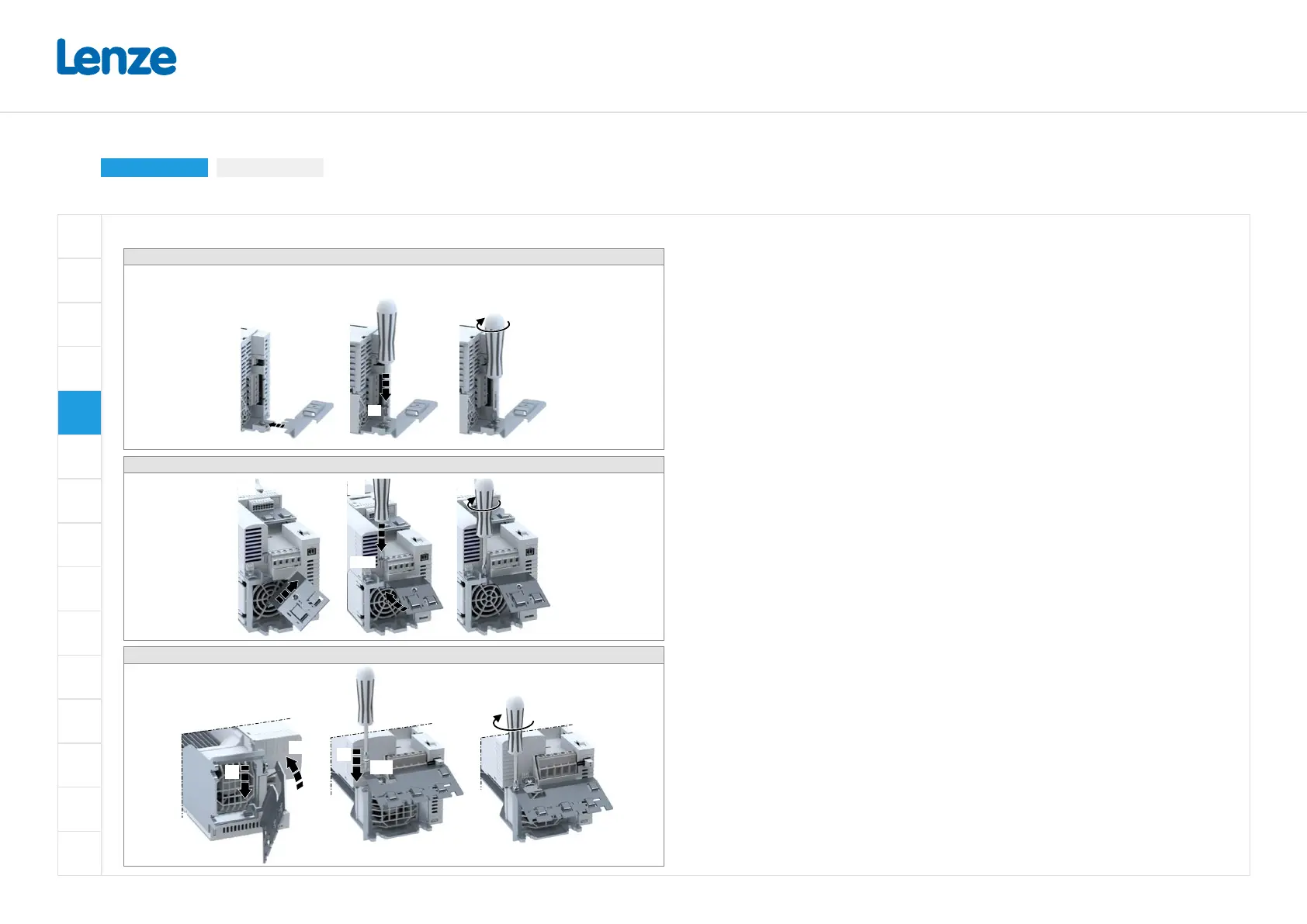
Mounting of shield connection sheet
I51xE125 ... I51xE240 (optional accessories)
Together with the inverter, the shield connection sheet is screwed onto the mounting plate.
3.4 Nm
(30 lb-in)
M5
I51AE255 ... I51AE311 (optional accessories)
2 Nm
(17.7 lb-in)
M4x12
I51BE275 ... I51BE311 (optional accessories)
2 Nm
(17.7 lb-in)
TX20
1.
2.
3.

Other manuals for Lenze i510

Questions and Answers:

Question and Answer IconNeed help?

Do you have a question about the Lenze i510 and is the answer not in the manual?

Lenze i510 Specifications

General IconGeneral
Product CategoryDC Drives
Seriesi510
Protection ClassIP20
CommunicationCANopen, Modbus RTU
Protection FeaturesOvervoltage, Undervoltage
Operating Temperature-10 to +50 °C
Storage Temperature-25 to +70 °C
Humidity5% to 95% (non-condensing)
Control ModeV/f control

Related product manuals