Do you have a question about the Lenze EtherNet/IP E84AYCEO and is the answer not in the manual?
Audience for whom the manual is intended.
Details on which devices and versions the documentation applies to.
Records changes and revisions made to the documentation.
Explains symbols, formatting, and terminology used in the manual.
Defines technical terms and acronyms relevant to the communication module.
Explains the meaning of signal words and symbols for safety and application notes.
Provides essential safety measures and general guidelines for using Lenze components.
Details safety precautions specific to the communication module and its applications.
Highlights potential risks and necessary protective measures during operation and installation.
Outlines the intended use and scope of the communication module.
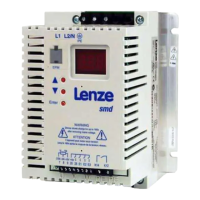
Explains how to identify the module using its nameplate information.
Lists key features and capabilities of the communication module.
Describes the physical connectors and interfaces available on the module.
Covers fundamental specifications and operating environment for the EtherNet/IP interface.
Details electrical insulation specifications and safety measures related to voltage.
Specifies supported protocol features and data formats for EtherNet/IP communication.
Explains runtime delays introduced by the integrated 2-port switch.
Provides physical dimensions of the communication module.
Covers the physical mounting procedures for the communication module.
Step-by-step guide for installing the module on specific device sizes.
Instructions for mounting the module on larger standard devices.
Procedures for removing and installing a new communication module.
Guidelines for connecting the module electrically.
Proper wiring practices to ensure electromagnetic compatibility.
Discusses common network configurations supported by EtherNet/IP.
Details how to establish the physical connection to the EtherNet/IP network.
Defines the required characteristics for Ethernet cables used with the module.
Provides pin assignments and wire color codes for Ethernet cable termination.
Explains how to provide an external power source for the module.
Procedures and precautions for the first power-up of the system.
Steps to configure the master device (scanner) for EtherNet/IP communication.
Information on Electronic Data Sheets required for device configuration.
A practical example of setting up IP configuration with a specific controller.
Method for setting network addresses using physical rotary switches on the module.
Overview of methods to assign IP addresses to the Inverter Drive 8400.
Using the Lenze »Engineer« software to configure IP settings.
Manually setting IP parameters using specific codes within the »Engineer« software.
Configuring IP addresses automatically using BOOTP or DHCP servers.
Details on configuring multicast settings for network communication.
Steps to establish a live connection for configuration and monitoring.
Procedures and precautions for the first power-up of the system.
Explains the different channels used for transmitting I/O and parameter data.
Describes the types of messages (implicit and explicit) used for data exchange.
Illustrates the operational states of the EtherNet/IP interface.
Details how I/O data is assigned to the module's internal ports.
Overview of supported drive profiles for controlling motor functions.
Using Lenze's technology applications and custom parameter configurations.
Specifics on using the AC Drive Profile for motor control.
Describes the structure and instances of I/O assemblies for data exchange.
How to configure I/O data using the Lenze »Engineer« software.
Configuring specific Lenze applications and custom parameters in »Engineer«.
Steps to configure the AC Drive Profile within the »Engineer« software.
Detailed steps for I/O configuration using older RSLogix 5000 versions.
Detailed steps for I/O configuration using newer RSLogix 5000 versions with EDS files.
Procedures for saving the configured I/O settings in RSLogix 5000.
How to write parameter values to the drive using explicit messages.
How to read parameter values from the drive using explicit messages.
Setting up reactions to communication faults in the »Engineer« software.
Information on interpreting the status indicators (LEDs) on the module.
Explanation of the ST, ER, and DE LEDs indicating module status.
Status indications provided by the MS and NS LEDs related to CIP communication.
Describes the Link and Act LEDs on the Ethernet ports for connection status.
Using the »Engineer« software to view detailed diagnostic information.
A table listing common EtherNet/IP error codes, their text, type, and response.
Detailed explanations of error causes and suggested solutions for troubleshooting.
Lists and describes error codes specific to the CIP protocol.
Correlates Lenze device errors with corresponding DRIVECOM error codes.
Lists and describes parameters specific to the E84AYCEO communication module.
Details of the parameter for setting the IP address of the module.
Information on the parameter used to define the subnet mask.
Description of the parameter for configuring the gateway address.
Parameter for displaying the module's MAC address.
Parameter to select the method for IP configuration (static, BOOTP, DHCP).
Parameter for setting the starting IP address for multicast groups.
Parameter to display the currently active IP address.
Parameter to display the active subnet mask.
Parameter to display the active gateway address.
Parameter to display the active multicast IP address.
Parameter for configuring Ethernet connection settings like baud rate.
Controls allocation of multicast IP addresses.
Sets the Time-To-Live value for multicast packets.
Sets the number of multicast IP addresses to be assigned.
Enables or disables the use of 802.1Q tags for QoS.
Configures DSCP values for data packet prioritization.
Displays the current Device Level Ring (DLR) network topology.
Shows the current status of the Device Level Ring (DLR) network.
Displays the IP address of the active ring supervisor.
Displays the MAC address of the active ring supervisor.
Displays beacon times in microseconds for DLR.
Displays beacon frame information for DLR ports.
Enables or disables Address Conflict Detection (ACD).
Displays the status of ACD.
Shows MAC ID of the last device with an address conflict.
Shows IP address of the last device with an address conflict.
Displays I/O data words transferred from module to scanner.
Displays I/O data words transferred from scanner to module.
Displays I/O data words transferred from scanner to the basic device.
Displays I/O data words transferred from module to the basic device.
Displays statistical data for Ethernet port traffic.
Shows the current status of the CIP module.
Displays the current status of the CIP network connection.
Shows the baud rate used on Ethernet connections.
Displays the current status of CIP connections.
Shows the type of each CIP connection.
Displays the trigger class for CIP connections.
Shows the Requested Package Interval (RPI) for CIP connections.
Displays timeouts for CIP connections.
Shows the run and idle flags for CIP connections.
Sets responses to faults in EtherNet/IP communication.
Sets the overall monitoring time for Ethernet communication.
Configures clearing of I/O data under specific conditions.
Parameter for setting the EtherNet/IP node's hostname.
Displays the firmware product type.
Shows the firmware compilation date and time.
Displays the firmware version of the module.
Indicates the current value set by rotary coding switches.
Overview of standard CIP objects implemented in the module.
Provides identification and general information about the device.
Handles data transfer services to any object class or instance.
Manages input/output data for scanner communication.
Manages resources for I/O and parameter data transfer.
Overview of EtherNet/IP specific objects.
Provides status information for the Device Level Ring protocol.
Enables classification and prioritization of data packets.
Configures the device's TCP/IP network interface.
Provides information about Ethernet interfaces and their status.
Objects specific to the AC Drive Profile application.
Provides data basis for motor parameters.
Describes management functions for motor control.
Describes drive-specific functions like speed ramps.
How to write the DriveMode attribute for torque control.
Lenze-specific objects for error response and data mapping.
Enables access to adjustable error responses.
Provides the image of the scanner input data.
Provides the image of the scanner output data.
Enables read/write access to Lenze codes.