4.4.8 POWERLINK
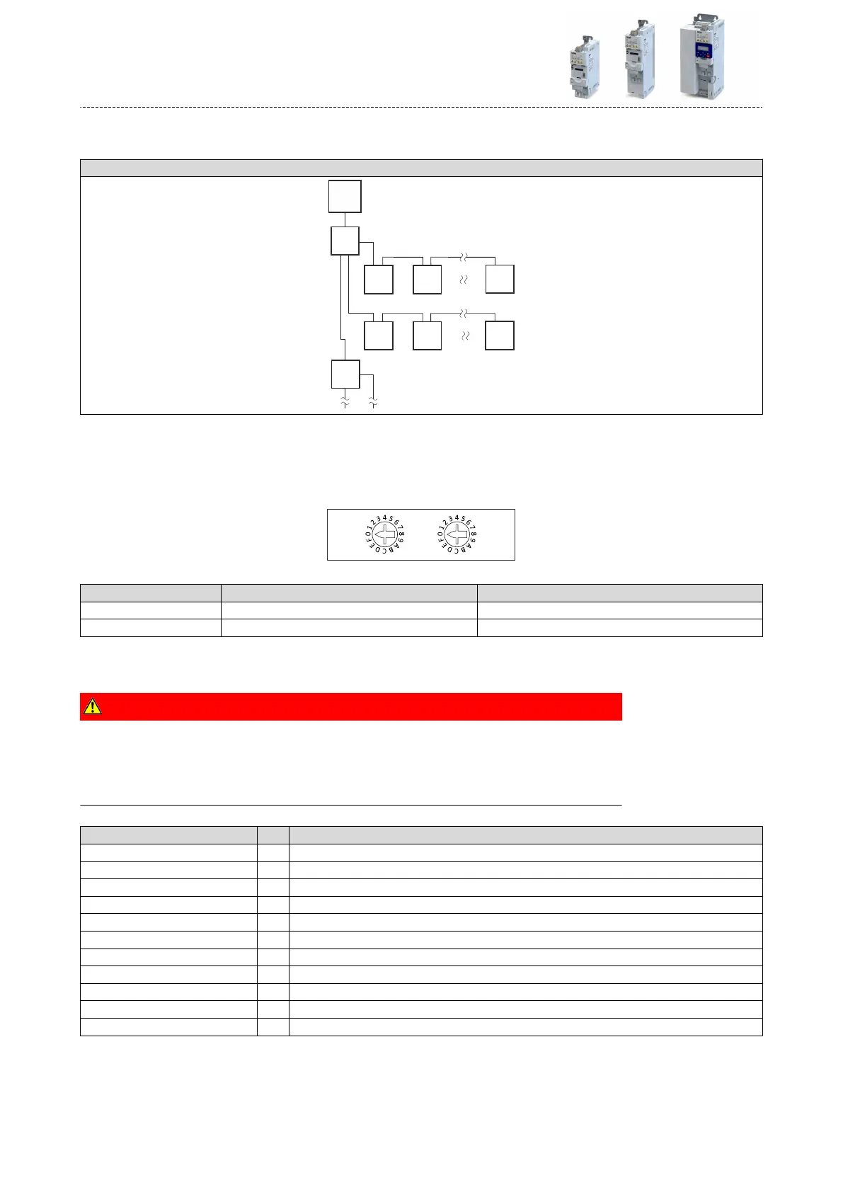
Typical topologies
Line
CN2n
CN22CN21
CN1n
CN12CN11
H2
H1
MN
Mrated Managing Node H Hub
CN Controlled Node
Basic network sengs
The rotary encoder switch allows you to set the node address (last byte of the IP address).
Seng Node address Resulng IP address
0x00 Value from parameter 192.168.100.<parameter value>
0x01 ... 0xEF Switch posion 192.168.100.<switch posion>
4.5 Connecon of the safety module
DANGER!
Automac restart if the request of the safety funcon is deacvated.
Possible consequences: Death or severe injuries
▶
You must provide external measures according to EN ISO 13849−1 which ensure that the
drive only restarts aer a conrmaon.
Terminal descripon Safety STO
Connecon X1
Connecon type pluggable spring terminal
Min. cable cross-secon mm² 0.5
Min. cable cross-secon AWG 22
Max. cable cross-secon mm² 1.5
Max. cable cross-secon AWG 16
Stripping length mm 9
Stripping length inch 0.35
Tightening torque Nm -
Tightening torque lb-in -
Required tool 0.4 x 2.5
Electrical installaon
Connecon of the safety module
70

 Loading...


