Operating instructions i550 cabinet frequency inverter | 20
© 11/2021 · EN · www.Lenze.com
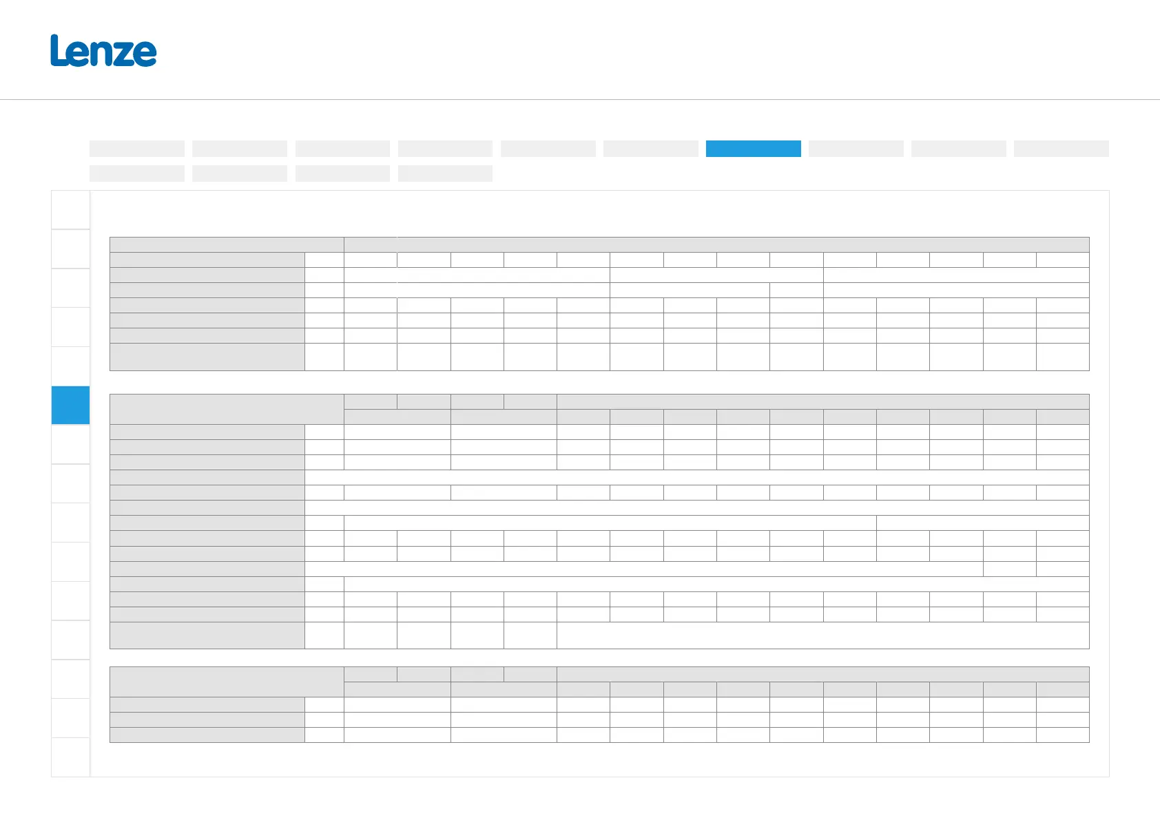
3-phase mains connection 480 V (340 V ... 528 V, 45 Hz ... 65 Hz), 7.5 ... 132 kW
Terminal data
Inverter I55xExxxF
Rated power kW 7.5 ... 11 15 ... 22 30 ... 45 55 ... 75 90 ... 110 7.5 ... 11 15 ... 22 30 ... 75 90 ... 110 7.5 ... 11 15 ... 22 30 ... 45 55 ... 75 90 ... 110
Connection Mains connection X100 PE connection Motor connection X105
Connection type Screw terminal Screw Bolt Screw terminal
Max. cable cross-section mm² 16 35 50 95 150 16 25 35 150 16 35 50 95 150
Stripping length mm 11 18 22 32 41 11 16 16 - 11 18 22 32 41
Tightening torque Nm 1.2 3.8 4 10 18 3.4 4 4 10 1.2 3.8 4 10 18
Required tool
0.8 x 4.0
0.8 x 5.5
5.0
6.0
8.0
PZ2
PZ2
PZ2
Size 13
key
0.8 x 4.0
0.8 x 5.5
5.0
6.0
8.0
Rated data (Heavy Duty) und fusing data
Inverter
I55AE I55BE I55AE I55BE I55AE
275F 311F 315F 318F 322F 330F 337F 345F 355F 375F 390F 411F
Rated power kW 7.5 11 15 18.5 22 30 37 45 55 75 90 110
Rated output current (8 kHz) A 14 21 27 34 40.4 52 65 77 96 124 156 180
Max. output current * A 28 42 54 68 81 104 130 154 192 248 312 360
Operation without mains choke
Rated mains current A 16.6 23.7 32.3 40.3 47.4 - - - - - - -
Fuse
Characteristic gG/gL, gRL gR
Max. rated current A 40 40 40 40 63 63 63 125 125 125 200 200 300 300
Max. short circuit current (SCCR) kA 65 65 65 65 65 65 65 22 22 22 22 22 22 22
Circuit breaker
Characteristic B, C
Max. rated current A 40 40 40 40 63 63 63 125 125 125 200 200 300 300
Max. short circuit current (SCCR) kA 65 65 65 65 65 65 65 35 35 35 35 35 10 10
Residual current device (RCD)
≥ 300 mA,
type B
≥ 30 mA,
type B
≥ 300 mA,
type B
≥ 30 mA,
type B
≥ 300 mA, type B
Rated data (light duty)
Inverter
I55AE I55BE I55AE I55BE I55AE
275F 311F 315F 318F 322F 330F 337F 345F 355F 375F 390F 411F
Rated power kW 11 15 18.5 22 30 37 45 55 75 90 110 132
Rated output current (4 kHz) A 18.3 25.2 32.4 40.8 48.5 62.4 78 92.4 115 149 187 216
Max. output current * A 28 42 54 68 81 104 130 154 192 248 312 360
* Overload time = 3s, recovery time = 12s
Electrical installation
3-phase | 480 V
3-phase | 230/240V
3-phase | 400 V1-phase | 120V
1-phase | 230/240V
Control terminals
Relay output
Connection diagram
Brake resistor
Networks
Functional safety
Safe torque o (STO)
PTC input
Preparation