Operating instructions i550 cabinet frequency inverter | 22
© 11/2021 · EN · www.Lenze.com
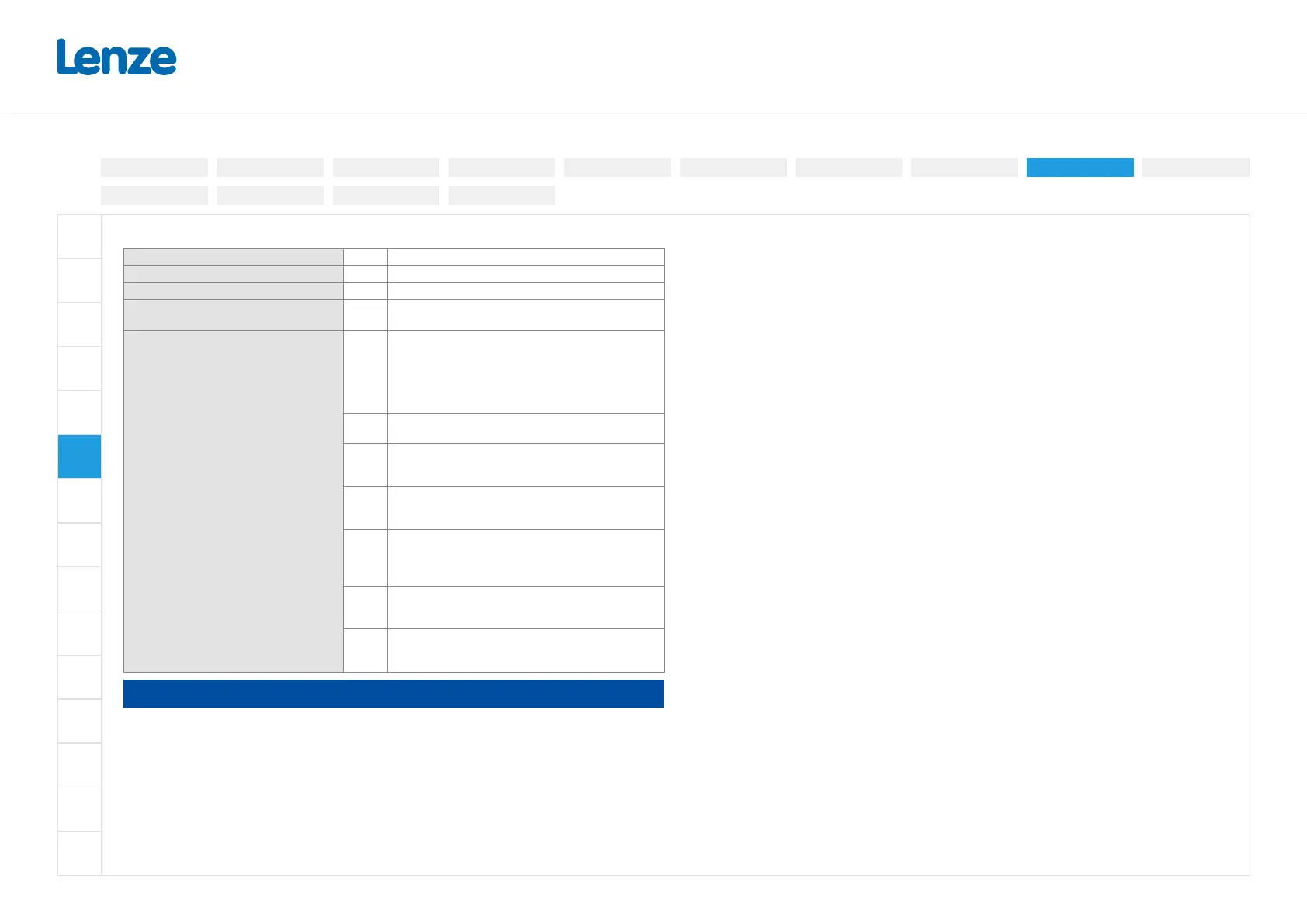
Control terminals X3
Connection type Spring terminal, pluggable
Max. cable cross-section mm² 1.5
Stripping length mm 9
Required tool
0.4 x 2.5
Application
DI1
DI2
DI3
DI4
DI5
Digital inputs
DI3/DI4 can optionally be used as frequency input or
encoder input.
HIGH active/LOW active switchable
LOW = 0 ... +3V
HIGH = +12V ... +30V
DO1
Digital output
Max. 100mA for DO1 and 24-V output
AI1
AI2
Analog inputs
Can optionally be used as voltage input or current
input.
AO1
Analog output
Can be optionally used as voltage output or current
output.
24E
24-V input
For mains-independent power DC supply of control
electronics (including communication).
Max.1A
10V
10-V output
Primarily for the supply of a potentiometer (1 ...10kΩ).
Max. 10mA
24V
24-V output
Primarily for the supply of digital inputs.
Max. 100mA for DO1 and 24-V output
NOTE
For voltage supply with DC 24V (± 20 %), use only a safely separated power supply unit in
accordance with prevailing SELV/PELV requirements.
Electrical installation
3-phase | 480 V
3-phase | 230/240V
3-phase | 400 V1-phase | 120V
1-phase | 230/240V
Control terminals
Relay output
Connection diagram
Brake resistor
Networks
Functional safety
Safe torque o (STO)
PTC input
Preparation