Electrical installation
Mounting steps
6
l
56
EDKRBS470R DE/EN/FR 10.0
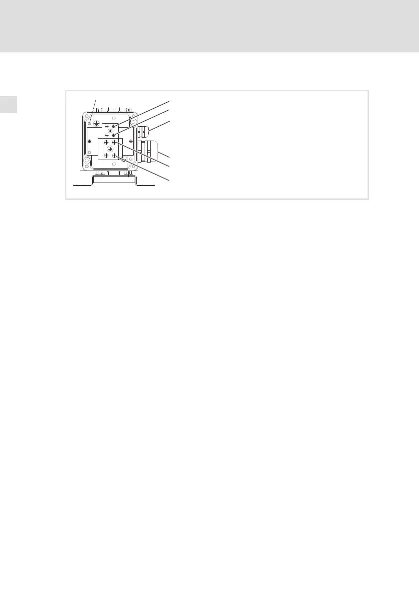
6.4 Mounting steps
1
0
RB1
T1
T2
RB2
PE
ERBSECS006
How to connect the brake resistor:
1. Disconnect the basic device from the mains and check that no voltage is
applied to the power terminals.
2. Remove the terminal cover.
3. Connect the brake resistor cable:
– Use a twisted cable for cables up to 0.5 m (connection plan variant 1).
– Use a shielded cable for cables up to 5 m (connection plan variant 2).
– Pass the cable through the cable gland 0.
– Connect the cores to connections RB1, RB2 and PE of the brake resistor
observing the tightening torque. PE connection to EN 61800−5−1.
– Tighten the cable gland 0.
For shielded cables: Securely connect the shield to the cable gland with
a surface as large as possible.
– Connect cores and shield to the basic device observing the
documentation for the basic device.
4. Connect the thermal contact cables:
– Use a twisted cable.
– Pass the cable through the cable gland 1.
– Connect the cores to connections T1 and T2 of the brake resistor
observing the tightening torque.
– Tighten the cable gland 1.
– When integrating the thermal contact into the system monitoring
ensure that the mains supply will be switched off when the brake
resistor is overheated.
5. Mount the terminal cover.
 Loading...

