Electrical installation
Terminal box
Cable glands for the fan terminal box
6
33
Lenze • BA 33.0006 • 5.1
Cable glands for the fan terminal box
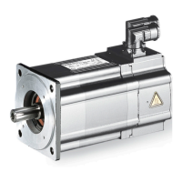
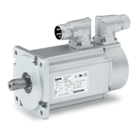
Motor type/size Screwed connection
MCA/MQA
20
1xM16x1.5
22
26
6.4.1 Power connections
MCA; MCS, MQA 20...22, MDKS
Contact Name Meaning
PE PE conductor
U
V
W
U
V
W
Motor winding phase U
Motor winding phase V
Motor winding phase W
TP1
TP2
TP1
TP2
PTC thermistor
TB1
TB2
TB1
TB2
Thermostat
Thermal NC contact
MCA 26, MQA 26
Contact Name Meaning
PE PE conductor
1
2
3
U1
V1
W1
Start of winding phase U
Start of winding phase V
Start of winding phase W
4
5
6
W2
U2
V2
End of winding phase W
End of winding phase U
End of winding phase V
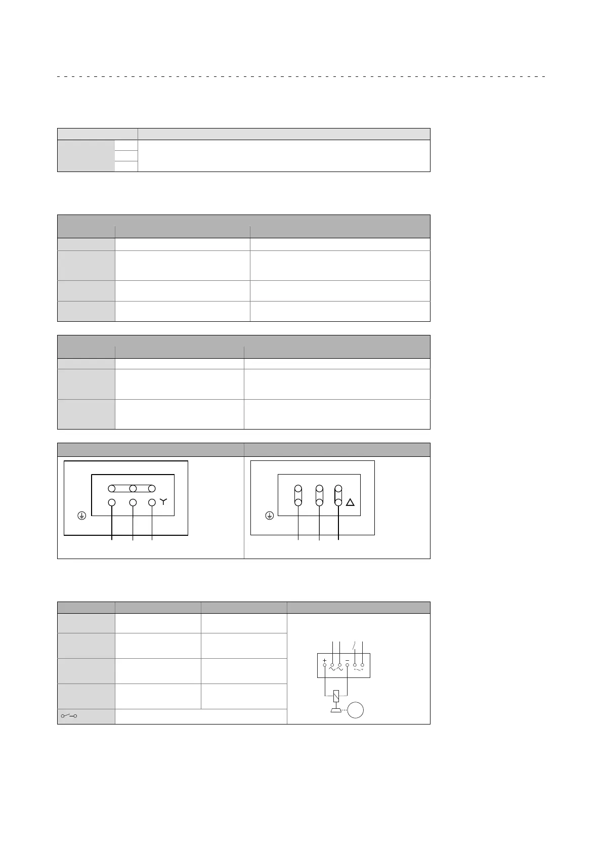
Star connection Delta connection
L1
L2
L3
PE
(W1)
(U1)
(V1)
(W2)
(U2)
(V2)
1
2
3
4
5
6
L1
L2
L3
PE
(W1)
(U1)
(V1)
(W2)
(U2)
(V2)
1
2
3
4
5
6
6.4.2 Holding brake DC 205 V - connected via rectifier (optionl)
Contact Name Meaning
BA1
Connection to L1 -
mains
AC-excited brake (rectifier)
BA2
Connection to N -
mains
M
3~
L1
N
+
BD1 (factory-set
wiring)
Connection of holding
brake +
-
BD2 (factory-set
wiring)
Connection of holding
brake -
Switching contact, DC switching