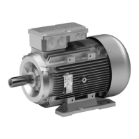
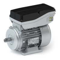
Electrical installation
Terminal box
Holding brake DC 24 V (optional)
6
34
Lenze • BA 33.0006 • 5.1
6.4.3 Holding brake DC 24 V (optional)
Contact Name Meaning
BD1
BD2
BD1
BD2
Holding brake +
Holding brake -
6.4.4 Fan
1-phase
Contact Name Meaning
PE PE conductor
U1
U2
U1
U2
Connection to L1 - mains
Connection to N - mains
3-phase
Contact Name Meaning
PE PE conductor
L1
L2
L3
U
V
W
Connection to L1 mains
Connection to L2 mains
Connection to L3 mains
6.4.5 Feedback system
Resolver
Contact Name Meaning
B1
B2
+Ref
-Ref
Transformer windings
(reference windings)
B3 +VCCENP Supply: electronic nameplate
1)
B4
B5
+COS
-COS
Stator winding cosine
B6
B7
+SIN
-SIN
Stator winding sine
B8 Not assigned
R1
R2
+KTY
-KTY
Thermal detector KTY
1) Only for versions with electronic nameplate ENP.
Incremental encoder / sin/cos absolute value encoder with Hiperface
Contact Name Meaning
B1
B2
+U
B
GND
Supply +
Mass
B3
B4
A
A
Track A / + COS
TrackAinverse/ -COS
B5
B6
B
B
Track B / + SIN
TrackBinverse/-SIN
B7
B8
Z
Z
Zero track / + RS485
Zero track inverse / - RS485
B10 Shield Encoder housing shield
R1
R2
+KTY
-KTY
Thermal detector KTY