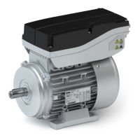
Connecon via M12 connector
Control connecons with M12 connectors
Via the digital inputs of the two M12 control connecons, it is possible to switch between
dierent speeds and direcons of rotaon. Up to 5 dierent speed sengs (e. g. creep speed
and normal speed in both direcons, as well as stop) can thus be selected. In addion, the
operang state is indicated via a digital output.
NOTICE
In the "DI/DO-GND bridged" version, the masses of the control terminal X1 and X2 (GND-I and
GND-O) are connected to each other. If only one speed is used, the connecon to X2 is
sucient.
Control connecon X1
M12 A coded X1
Contact Name Meaning
1 n.c.
2 DI2 Digital input 2
3 GND-I Ground of digital input
4 DI1 Digital input 1
Control connecon X2
M12 A coded X2
Contact Name Meaning
1 24V 24 V supply (DO1 supply)
2 DI3 Digital input 3 (reference X1;3 = GND-I)
4 DO1 Digital output 1
3 GND-O Ground of digital output
Connecon data - digital inputs for control connecon X1/X2
Name Supply voltage Internal resistance
V
in
R
i
DC V Ω
DI1
24 (19.2 ... 28.8) 5600DI2
DI3
Product extensions
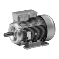
Motor connecon
Connecon via M12 connector
44
 Loading...