Perform the following steps for a more precise
Ambient Light adjustment (see Figure 4):
1. Make the adjustment when the actual ambient light
is at the level where no artificial light is required.
2. Turn the Ambient Light adjustment to the (-) position
(minimum light).
3. Turn the Time-Delay adjustment to the (-) position
(at 20 seconds) and leave the monitored space.
4. Re-enter the monitored space after the lights go
OFF and the lights will remain OFF.
5. Slowly turn the Ambient Light adjustment knob
towards (+) until the lights go ON.
6. Slightly turn the Ambient Light adjustment knob
back towards (-) and leave the monitored space.
7. When you return to the monitored space, the lights
should remain OFF. If the lights come ON, repeat
step 6 until the lights remain OFF when you re-
enter the monitored space, at the desired ambient
light level.
8. Reset the Time-Delay adjustment back to the
desired position.
TROUBLESHOOTING
• LIGHTS WILL NOT TURN ON
- Circuit breaker or fuse is OFF: Turn the breaker
ON. Ensure that lights being controlled are in working
order (i.e., working bulbs, integral switches ON, etc.).
- Sensor is wired incorrectly or may be
defective: Confirm that the sensor’s wiring is
done exactly as shown in the diagram and/or
inspect it visually for problems.
- Lens is dirty or obstructed: Inspect the lens
visually and clean if necessary, or remove the
obstruction.
• Ambient light setting is for a darker
background than that present: Adjust the
Ambient light setting.
• LIGHTS WILL NOT TURN OFF
- Sensor is wired incorrectly or may be
defective: Confirm that the sensor’s wiring is
done exactly as shown in the diagram and/or
inspect it visually for problems.
- Sensor may be mounted too closely to an air
conditioning or heating vent, or traffic in an
adjacent area is affecting sensor: Move the
sensor to another location, or close the vent.
- The line voltage has dropped: Perform the
necessary tests to ensure the line voltage has not
dropped beneath 100V. If it has dropped, check
for operation of any large appliances on the
circuit, and turn them off.
- Light is being reflected from an object: Check
the area for any white or shiny surfaces that might
be reflective, and correct the situation.
• LIGHTS TURN OFF AND ON TOO QUICKLY
- Sensor may be mounted too closely to an air
conditioning or heating vent: Move the sensor
to another location, or close the vent.
- Light being reflected from an object: Check the
area for any white or shiny surfaces that might be
reflective, and correct the situation.
- Time delay set improperly: Adjust the TIME
DELAY (see SETTINGS section)
.
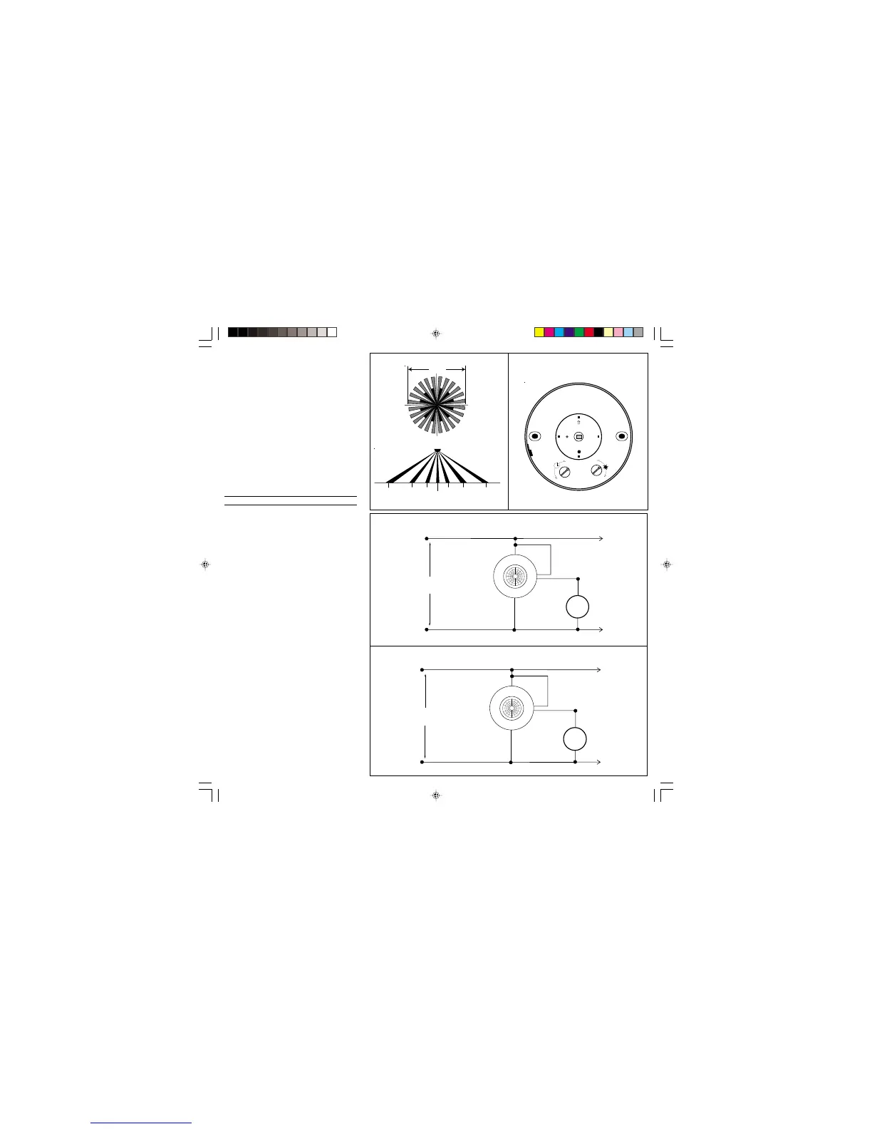
Hot (Black)
Neutral (White)
Sensor
Load
Black
White
Black
White
Blue
Blue
Line
120VAC, 60Hz
Hot (Black)
Neutral (White)
Load
Black
White
Red
White
Blue
Blue
Line
277VAC, 60Hz
Sensor
Wiring Diagram 2 - Cat. No. ODC0S-I7
Wiring Diagram 1 - Cat. No. ODC0S-I1
1M
3 FT
1
2 M
7 FT
2
3.7 M
13 FT
3
1M
3 FT
1
2 M
7 FT
2
3.7 M
13 FT
3
0
0
Figure 3A - Field-of-View (Horizontal)
26 Ft.
 Loading...