OSFLO ADAPTER INSTALLATION:
1. Position the adapter half with the insert nipple to the end of the luminaire or electrical box to determine if
sensor will be positioned correctly for optimum coverage.
2. If appropriate position for coverage, insert the snap fitting into the knockout of the luminaire or electrical
box (if added depth is needed for coverage, use the OSFOA with multiple positions).
3.
Remove the locknut from the sensor and insert the wire leads through the mounting hole of the other half
of the adapter. Slide locknut over wire leads and thread onto threaded sensor nipple and tighten so that
sensor does not move. Align sensor so that it is parallel to the bottom of the luminaire or electrical box.
4. Feed the sensor wire through the adapter half mounted on the luminaire or electrical box and into the
wire access area.
5. Snap the adapter half with the sensor attached to the adapter half on the luminaire or electrical box by
aligning the snap fittings and pushing firmly together
.
6. Connect per Wiring Diagram as follows: BLACK lead to LINE (Hot), RED lead to LOAD, WHITE
lead to LINE (Neutral). Twist strands of each lead tightly and with circuit conductors, push firmly into
appropriate wire connector. Screw connector on clockwise making sure no bare wires show below
the connector.
7. Restore power at circuit breaker or fuse.
NOTE: Allow approximately 1 minute for charge-up. If the lights turn ON and the LED blinks when
a hand is waved in front of the lens, then the Sensor was installed properly. If the operation is
different, refer to the Troubleshooting Section.
SETTINGS
Time-Delay: Settings should be determined during the installation
period. This adjustment controls the amount of time the lights stay
ON after the last detected motion. You may select settings varying
from 30 seconds to 20 minutes and any time in between.
NOTE: After power is turned ON, allow two minutes for this unit to
warm up before performing Time-Delay settings.
TROUBLESHOOTING
• Lights will not turn ON
- Circuit breaker or fuse is OFF: Turn the breaker ON. Ensure the lights being controlled are in
working order (i.e., working bulbs, ballasts, etc.)
- Sensor is wired incorrectly or may be defective: Confirm that the sensor’s wiring is done
correctly and inspect visually for problems.
- Lens is dirty or obstructed: Inspect the lens visually and clean if necessary, or remove the
obstruction.
• Lights will not turn OFF
- Sensor is wired incorrectly or may be defective: Confirm that the sensor’s wiring is done
correctly and inspect visually for problems.
- Sensor may be mounted too closely to an air conditioning or heating vent: Move the
sensor or close the vent.
- The line voltage has dropped: Perform the necessary tests to ensure the line voltage has not
dropped beneath 100V.
• Lights turn OFF and ON too quickly
- Sensor may be mounted too closely to an air conditioning or heating vent: Move the
sensor to another location or close the vent.
- Time delay set improperly: Adjust the TIME DELAY.
PK-93439-10-00-5H
Wiring Diagram
Hot (Black)
Neutral (White)
Load
Red
White
White
Sensor
Black
Black
Line
120-347VAC,
50-60Hz
30 SEC.
20 MIN.
TIME DELAY
10
15
5
Timer
dial
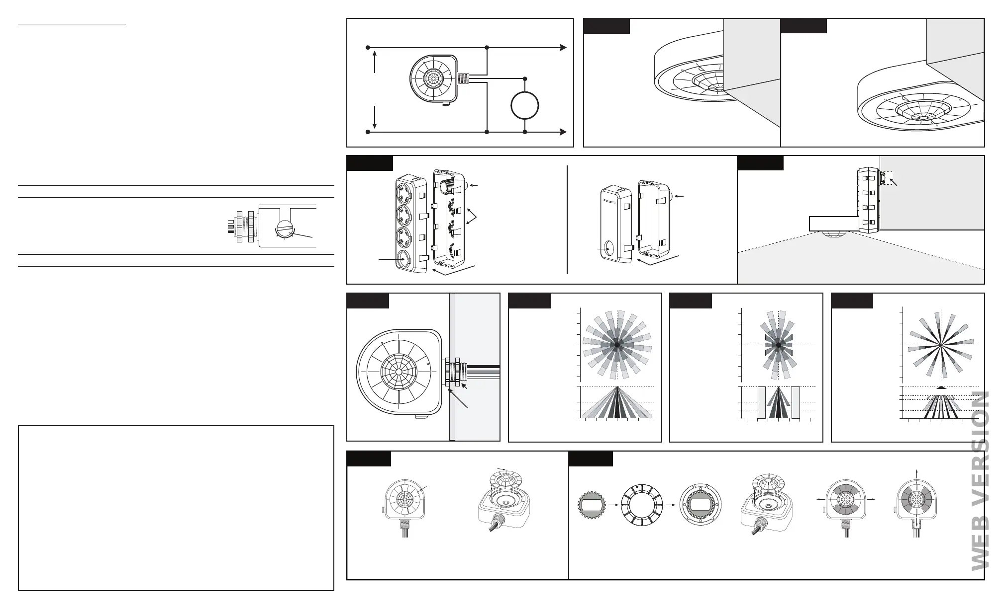
Figure 2A
Sensor
mounts
here
(non-keyed) hole
Wires from
sensor to
luminaire or
electrical
box are fed
through adapter
Alternate keyholes
for height adjustment
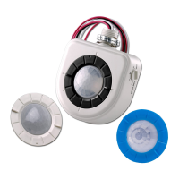
OSFOA-00W
Adapter
Threaded snap-in nipple
attaches to 1/2" luminaire
or electrical box trade-size
knockout holes
Wires from
sensor to
luminaire or
electrical
box are fed
through adapter
Insert nipple
attaches to
1/2" luminaire
or electrical box
trade-size
knockout holes
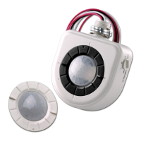
Sensor
mounts
here
(non-keyed)
hole
OSFLO-00W
Adapter
Figure 2B
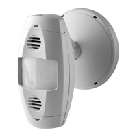
OSFOA-00W
Adapter
(shown)
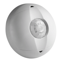
Sensor
Adapter allows sensor to be mounted
to achieve optimum field-of-view
1/2"
trade-size
knockout
hole
© 2021 Leviton Mfg. Co., Inc.
Figure 7A Figure 7B
Line up dots
Dots
Pull up on tab to remove 360
˚
lens
(High Bay or Low Bay)
Tab
Positon aisle mask for applicationInsert aisle mask into lens assembly
(if applicable)
Line up dots and
turn to set lens
Figure 1B
Figure 1A
Sensor mounted too high
Outer beams are obstructed
Field-of-view is limited
INCORRECT
Sensor mounted within 1" of bottom
No obstruction
Optimum field-of-view
CORRECT
FCC Statement: This equipment has been tested and found to comply with the limits for a Class B digital device,
pursuant to part 15 of the FCC Rules. These limits are designed to provide reasonable protection against harmful
interference in a residential installation. This equipment generates, uses and can radiate radio frequency energy and,
if not installed and used in accordance with the instructions, may cause harmful interference to radio communications.
However, there is no guarantee that interference will not occur in a particular installation. If this equipment does cause
harmful interference to radio or television reception, which can be determined by turning the equipment off and on, the
user is encouraged to try to correct the interference by one or more of the following measures:
• Reorient or relocate the receiving antenna.
• Increase the separation between the equipment and receiver.
• Connect the equipment into an outlet on a circuit different from that to which the receiver is connected.
• Consult the dealer or an experienced radio/TV technician for help.
FCC CAUTION
Any changes or modifications not expressly approved by Leviton Manufacturing Co., could void the user’s authority
to operate the equipment.
IC Statement: This device complies with Industry Canada license-exempt RSS standard(s). Operation is subject
to the following two conditions: (1) this device may not cause interference, and (2) this device must accept any
interference, including interference that may cause undesired operation of the device.
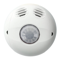
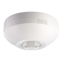
FCC Suppliers Declaration of Conformity (sDoC): High Bay/Low Bay Passive Infrared Occupancy Sensor and Offset
Adapter are manufactured by Leviton Manufacturing, Inc., 201 N Service Road, Melville, NY 11747. www.Leviton.com.
This device complies with part 15 of the FCC Rules. Operation is subject to the following two conditions: (1) This
device may not cause harmful interference, and (2) this device must accept any interference received, including
interference that may cause undesired operation.
Figure 4
9.1m (30 ft)
9.1m
(30 ft)
9.1m
(30 ft)
9.1m (30 ft)
9.1m (30 ft)
12.2m (40 ft)
6.1m (20 ft)
6.1m
(20 ft)
6.1m
(20 ft)
6.1m (20 ft)
6.1m (20 ft)
3m (10 ft)
3m (10 ft)
3m
(10 ft)
3m
(10 ft)
0
0
0
White
High Bay
360
˚
Top View
Side View
Figure 5
9.1m (30 ft)
9.1m
(30 ft)
9.1m
(30 ft)
9.1m (30 ft)
9.1m (30 ft)
12.2m (40 ft)
6.1m (20 ft)
6.1m
(20 ft)
6.1m
(20 ft)
6.1m (20 ft)
6.1m (20 ft)
3m (10 ft)
3m (10 ft)
3m
(10 ft)
3m
(10 ft)
0
0
0
Side View
S
H
E
L
V
E
S
S
H
E
L
V
E
S
Figure 6
Blue
Low Bay
360
˚
Top View
Side View
Aisle Mask
Top View
Figure 3
Inside of
Luminaire
or
Electrical
Box
Sensor
Wires
Tightening
Lock-Nut
Stopping
Lock-Nut
9.1m (30 ft)
9.1m (30 ft)
6.1m (20 ft)
6.1m (20 ft)
3.0m (10 ft)
3.0m (10 ft)
0
6.1m (20 ft)
7.6m (25 ft)
2.4m (8 ft)
0
3.7m (12 ft)
9.1m
(30 ft)
9.1m
(30 ft)
6.1m
(20 ft)
6.1m
(20 ft)
3.0m
(10 ft)
3.0m
(10 ft)
0
*Not recommended for aisleway applications under 12ft mounting height
 Loading...