Do you have a question about the Lewmar AutoAnchor 150 and is the answer not in the manual?
Details electrical and physical specifications including power supply, current consumption, IP rating, and voltage.
Covers cable sizes and specific requirements for rope/chain connections, including resistor needs.
Outlines power supply requirements, connection precautions, and the need for a shut-off switch.
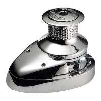
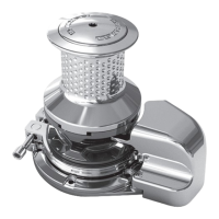
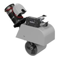
Crucial steps for installing magnets and sensors on windlasses for accurate operation.
Guidance on selecting a suitable location and mounting the console unit for optimal visibility and protection.
Instructions for connecting cables, including precautions for interference and multiple console setups.
Procedure for accessing the setup menu, including button presses and version number display.
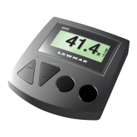
How to choose between feet and metres for rode measurement display.
Options for selecting windlass type: custom chain, custom rope/chain, or pre-programmed profiles.
Ensuring the device is correctly set up for the windlass and rode before initial use.
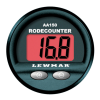
How the AA150 displays rode length, remembers settings, and provides alerts during retrieval.
Adjusting the console display brightness for optimal visibility in different lighting conditions.
Procedure to zero the current rode count display.
Restoring the unit to its original factory settings, removing custom configurations.
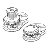
The AutoAnchor 150 (AA150) V1.34 is a sophisticated rode counter designed to assist with anchoring operations on boats. It functions as a digital display for the length of anchor rode (rope and/or chain) deployed, enhancing safety and convenience for the operator. The device is compatible with most vertical windlasses and some horizontal windlasses, though horizontal installations may require additional components like a sensor holder or custom-designed sensor.
The primary function of the AA150 is to measure and display the length of anchor rode deployed from the windlass. It can operate with either chain-only or rope and chain rode configurations. The unit does not directly control the windlass; instead, it works in conjunction with existing windlass controls such as a toggle switch, deck switch, or handheld remote. When the windlass is operated, the AA150 automatically turns on and displays the deployed rode length. A key safety feature is an audible beep that sounds when the anchor is within 1.5 meters (4 feet) of docking during retrieval, alerting the skipper. The device retains its settings and the current count even when power is turned off. For accurate counting, the system relies on a magnet installed in the chainwheel and a sensor positioned to detect the magnet's rotations as the rode passes.
The AA150 offers a "Set Up Mode" for initial configuration, allowing the user to select measurement units (feet or meters) and input specific windlass and rode parameters. This includes the length of chain per turn and rope per turn, which can be calculated using a detailed measurement procedure outlined in the manual or selected from a list of pre-programmed windlass profiles.
The device also includes diagnostic messages (e.g., Sn 1, Sn 2, Sn 3, Sn 4, Ld) that appear briefly during operation or power-up to indicate potential issues with the installation, sensor, or wiring. These messages are accompanied by a beep and are cleared after a few seconds. The AA150 also features adjustable backlight levels for optimal visibility in various lighting conditions and options to reset the display to zero or restore factory default settings.
The AA150 is designed with no user-serviceable internal parts. Maintenance is limited to external checks and cleaning:
The manual emphasizes the importance of correct installation by a qualified marine electrician and adherence to all technical and cable specifications to ensure proper operation and maintain warranty validity. It also highlights that the AA150 is a counting device and does not replace good seamanship and safe boating practices during anchoring.
| Brand | Lewmar |
|---|---|
| Model | AutoAnchor 150 |
| Category | Marine Equipment |
| Language | English |