2
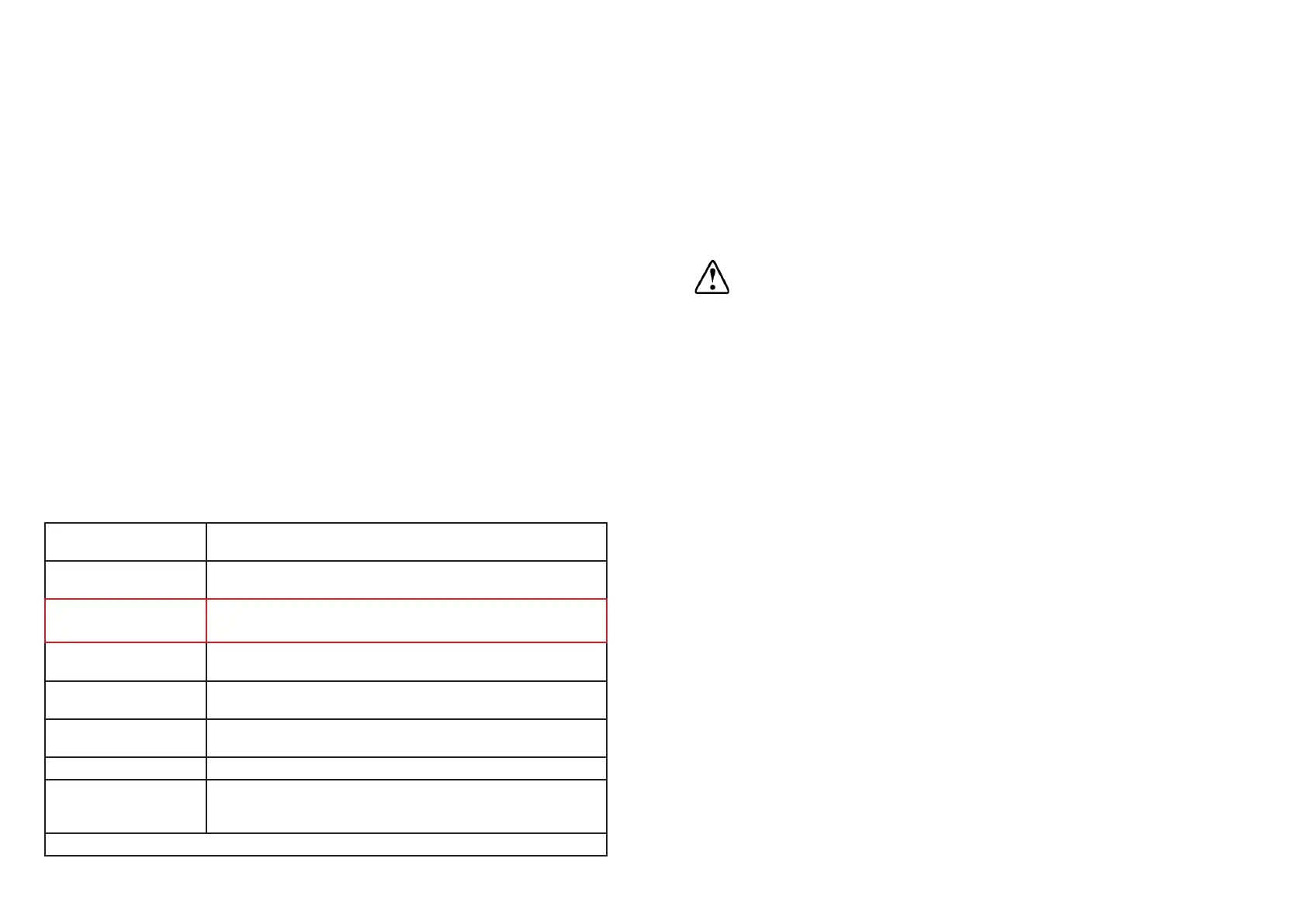
Power Supply
Current Consumption 30mA
IP Rating
protected from moisture.
Operating Temperature
Range
23
o
F to 140
o
F (-5
o
C to 60
o
C)
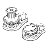
Sensor Compatible with all AutoAnchor sensors, reed switches and
Rode - Chain Only
Rode - Rope and Chain
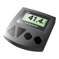
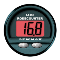
1.1 TECHNICAL SPECIFICATIONS AA150
ELECTROMAGNETIC COMPATIBILITY (EMC)
FCC Information:
ESTI Information (CE):
These
emission generating products on the boat. Compliance with these standards is no
guarantee that interference will not occur in a particular installation. The installation
instructions must be followed to minimise the potential for interference.
Note: If shielded cable is not used for the sensor connections this will compromise the
The AA150 console must be installed at least 3 ft (1m) away from any transmission
equipment or cables carrying radio signals eg VHF radios, cables and antennas or radar
antennas; and at least 6 ft (2m) away from any SSB equipment. AA150 cables must be
installed at least 1.5ft (500mm) away from such items.
3
1.3 POWER SUPPLY
MAKING ANY CHANGES TO WIRING OR ELECTRICAL CONNECTIONS.
Check battery polarity before connecting power.
The power must be disconnected when installing and connecting the wiring.
A 5 Amp resettable isolating/breaker switch to shut off power to the AA150 and the
windlass must be installed in a position easily accessed by the AA150 operator.
Power to the AA150 and all windlass controls eg. toggle switch, remote switches, deck
switches must be supplied from one point or the AutoAnchor will be damaged.
1.2 CABLE SPECIFICATIONS
All Cables: 1.0mm
2
(AWG18)
Rope/Chain Connections: If the brown and white wires are connected to the motor
terminals for rope/chain counting short circuit protection is required. The load sensor
 Loading...