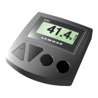
2.1.3 PLUG AND PLAY SENSOR CABLE
to the console unit.
The warranty does not apply if the sensor cable plugs are removed.
6.5 m (21.33 ft) Part #9500
10 m (32.81 ft) Part #9501
15 m (49.21 ft) Part #9502
20 m (66.62 ft) Part #9503
25 m (82 ft) Part #9504
35 m (114.83 ft) Part #9514
4
PART 2 INSTALLATION
2.1 MAGNET AND SENSOR INSTALLATION
PLEASE READ BEFORE COMMENCING INSTALLATION
Correct magnet and sensor installation is critical for successful AutoAnchor
operation.
Installation differs depending on the windlass type and on the rode (all-chain or rope and
chain). Please follow the instructions for your windlass and rode. If it is not possible
to comply with these instructions please check with the AutoAnchor manufacturer or your
supplier for other options or if you are not sure how to proceed.
See www.autoanchor.co.nz for contact information.
2.1.1 MAGNET INSTALLATION OVERVIEW
Check before starting:
Magnet Polarity:
the magnet must face the sensor.
Magnet Seal:
to protect it against corrosion.
Magnet Size and Position:
2.1.2 SENSOR INSTALLATION OVERVIEW
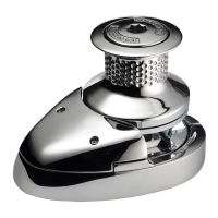
Vertical Windlasses:
If the windlass is not factory drilled, drill a hole 10.3 mm (13/32”) diameter through the
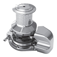
Horizontal Windlasses: Sometimes it is not possible to t the sensor to a horizontal
windlass or it may need to be tted by the windlass manufacturer. Before starting
check with the AutoAnchor manufacturer or supplier that it is possible to t the
sensor to your windlass. You may need a special tting.
Drilling the Deck: Before drilling into the deck, ensure there is nothing below the deck that
could be damaged and that any hole you drill will not weaken the boat’s structure
hole 10.3mm (13/32”) diameter through the deck. Ensure this hole is directly in line with the
sensor hole in the deckplate.
5
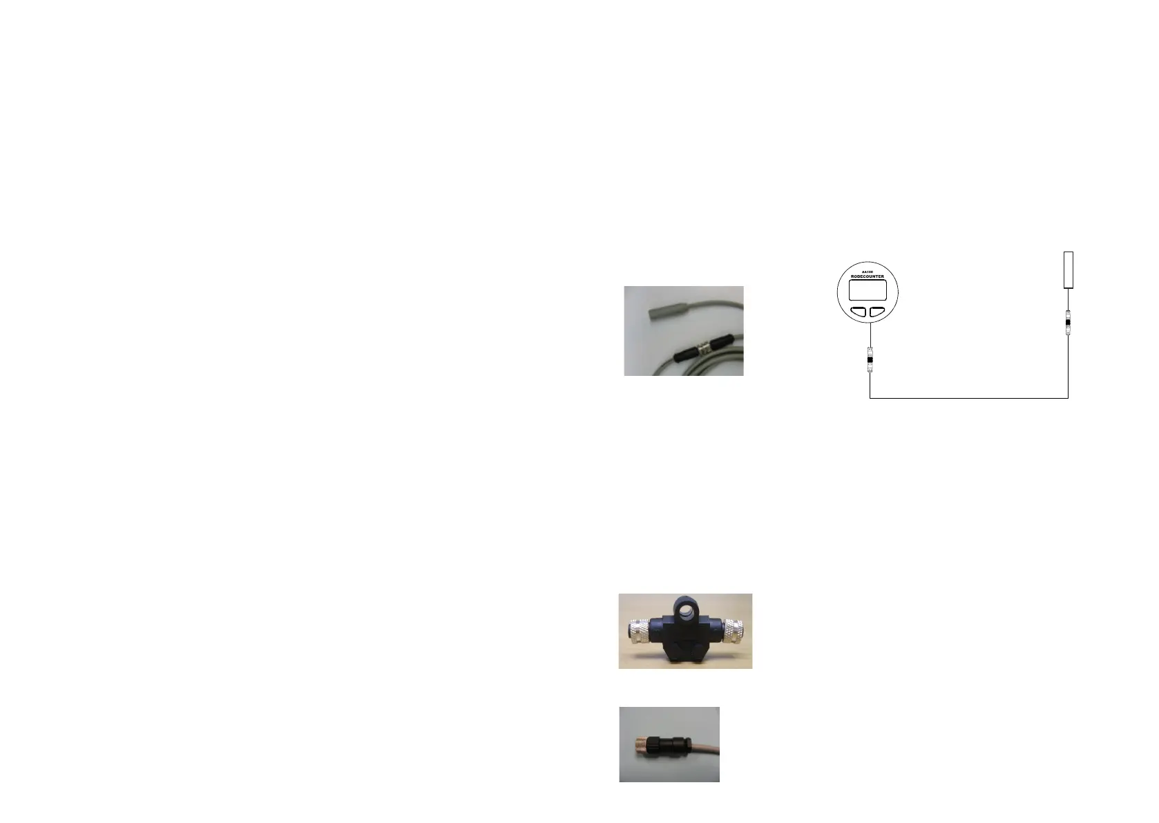
Part #9507 Male Field Connector
Part #9508 Female Field Connector
Connecting 2 cables together:
joined together using Part #9510 Gender changer.
Sensor Connecting Cable
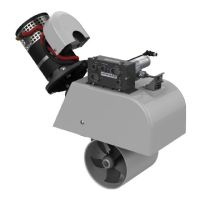
Fitting the Sensor:
can damage the internal electronics. Ensure the sensor head is positioned so that it will not
be hit by the chainwheel during windlass operation and that it is at least 300mm (1ft) away
from the battery and motor cables. Secure the sensor using a good quality neutral cure
Field Connectors
 Loading...