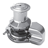
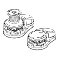
The Lewmar Pro-Series & Pro-Fish Windlass is a marine anchoring system designed for reliable and efficient anchor control in various marine applications. This owner's manual (B10490 Issue 1) provides comprehensive instructions for installation, operation, and basic servicing of both Pro-Series and Pro-Fish models, including the 700 and 1000 series.
Function Description:
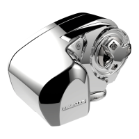
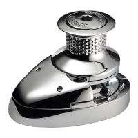
The primary function of the windlass is to assist in the deployment and retrieval of anchors and anchor rodes (rope and/or chain). It automates the physically demanding task of hauling in the anchor, making anchoring safer and more convenient. The Pro-Series models feature a clutch for manual control of anchor deployment, while the Pro-Fish models offer a "freefall" mode for rapid anchor deployment under gravity, with the option to convert to a power-down mode similar to the Pro-Series. The windlass is designed to handle rope/chain combination rodes, with specific gypsies tailored for different rope and chain sizes.
Important Technical Specifications:
The windlass is available in two main models: 700 and 1000, both operating on a 12V electrical system.
-
Model 700:
- Maximum Pull: 320 kg (700 lb)
- Maximum Line Speed: 32 m/min (105 ft/min)
- Typical Working Load: 80 kg (175 lb)
- Normal Line Speed: 27 m/min (88 ft/min)
- Boat Size: Up to 10.7 m (35 ft)
- Gypsy Options: RC0762 for 7 mm (1/4") High Test G-4 ISO chain and 12 mm or 1/2" 3-strand medium lay or 8-plait nylon rope; RC0670 for 6 mm (NON USA) chain and 12 mm (NON USA) rope.
- Breaker/Isolator: 50 A (Part No. 68000348)
- Control Switch: Toggle Switch (Part No. 0052519)
-
Model 1000:
- Maximum Pull: 454 kg (1000 lb)
- Maximum Line Speed: 32 m/min (105 ft/min) 12V
- Typical Working Load: 114 kg (250 lb)
- Normal Line Speed: 27 m/min (88 ft/min) 12V
- Boat Size: Up to 13.7 m (45 ft)
- Gypsy Options: RC0850 for 8 mm (5/16") High Test G-4 ISO chain and 14-16 mm or 9/16"-5/8" 3-strand medium lay or 8-plait nylon rope.
- Breaker/Isolator: 70 A (Part No. 68000240)
- Contactor: (Part No. 0052531)
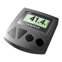
- Control Switches: Deck Foot Switch Set (68000598 Black, 68000597 White), Hand Held Control (68000599), Guarded Rocker Switch (68000593).
Electrical Wiring:
Proper electrical cable selection is crucial to ensure optimal performance and prevent voltage drop, which should not exceed 10%. Cable length is measured from the battery to the windlass and back to the battery. The manual provides detailed cable size recommendations (mm² and AWG) based on total cable run for both 700 and 1000 models. The wiring system is a two-cable, fully insulated return type, utilizing stranded, tinned copper wire with crimp terminals. Overload protection is provided by a circuit breaker/isolator, which must be installed in a dry, accessible location. For Model 1000, a contactor is also required and must be sited in a dry location.
Usage Features:
- Gypsy Suitability: Designed for Lewmar factory-made rope/chain combination rodes. Users are advised to experiment with ropes and chains from other manufacturers to determine optimum size.
- Clutch Operation (Pro-Series): A clutch nut, tightened clockwise with the supplied wrench, locks the gypsy to the gear train for hauling. Slackening anticlockwise frees the gypsy for manual deployment.
- Clutch Operation (Pro-Fish Freefall): Pressing the DOWN button for 2 seconds initiates freefall. Continuous UP button press re-engages the internal clutch mechanism.
- Letting Go Under Gravity: Requires tightening the clutch, releasing anchor locks, and controlling descent with the clutch lever.
- Letting Go Under Power: Release anchor locks and operate a down control.
- Pro-Fish Power Down Mode: The Pro-Fish Plunger can be locked in with the Stopper to convert the unit to a standard power-down mode.
- Lying to Anchor Safely: The anchor rode must be made fast directly to a bollard, sampson post, or cleat to prevent excessive loads on the windlass.
- Hauling In: Operate an 'Up' control. The vessel's engine can assist in moving towards the anchor.
- Manual Recovery: A standard 12 mm (1/2") drive ratchet can be inserted into the driveshaft socket for manual retrieval.
- Operating Tips: Powering the rode out is recommended when anchoring. Inching the anchor in as it approaches the stemhead prevents damage. An anchor safety strap or chain stopper is advised.
- Joining Rope to Chain: Detailed instructions are provided for splicing rope to chain to minimize chafe, emphasizing regular checks for wear.
Maintenance Features:
- Regular Checks: After initial use, mounting nuts should be checked for tightness. The exterior of the windlass should be regularly washed with fresh water.
- Electrical Connections: Examine for corrosion, clean, and lightly grease as needed.
- Rode Splice: The anchor rode splice should be checked regularly and remade if there is any evidence of wear.
- Gypsy Examination: The gypsy, a high-wear item, should be examined regularly.
- Dismantling Procedures: Detailed instructions are provided for:
- Gypsy Replacement: Specific steps for both Pro-Series and Pro-Fish models, including clutch nut removal, drive pin handling, and stripper removal. Pro-Fish gypsy replacement involves shoulder screw, washer, drive cap, and stopper cam removal. Loctite® 638 is recommended for reassembly of the shoulder screw on Pro-Fish models.
- Control Arm Replacement: Involves removing grub screws, pivots, and torsion springs.
- Gypsy Drive Shaft Replacement & Lubrication Service: The gear train is pre-lubricated with SFG 100 grease. External drive shaft components should be stripped, cleaned, and re-greased annually. Instructions for removing the gear train cover, compound gear assemblies, external circlip, and drive shaft are provided. The wiper seal should be inspected and replaced if unserviceable. Reassembly requires generous amounts of grease.
- Electric Motor Replacement: Requires disconnecting motor cables, removing the gear train cover, motor screws, and carefully withdrawing the motor. Fresh silicone and Loctite® 2701 threadlock are used for reassembly.
- Pro-Fish Conversion: Pro-Series units (from Serial Number 0603 or later) can be converted to Pro-Fish units using a specific conversion kit (66000616).
- Troubleshooting: Charts are provided for diagnosing and resolving common issues such as anchor rode paying out independently, sluggish operation, and general electrical failures.
Safety Notices:
The manual emphasizes safety throughout, including warnings about potential injury from moving parts, the importance of securing the anchor rode independently of the windlass, and the need for proper electrical installation by qualified personnel. It also highlights the importance of regular maintenance and examination of the windlass due to its exposed marine environment.