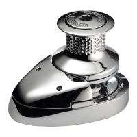
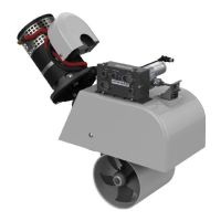
The Lewmar 3500 Gypsy/Drum Windlass is a robust anchoring system available in both electric and hydraulic vertical models, designed for marine applications. This manual provides comprehensive installation, operation, and maintenance guidelines to ensure reliable performance and longevity.
Function Description:
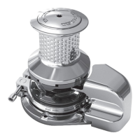
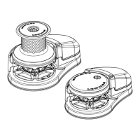
The windlass is primarily used for raising and lowering anchors and their associated chain or rope. It features a gypsy/drum configuration, allowing for the handling of both chain (via the gypsy) and rope (via the drum or capstan). The main shaft, driven by either an electric motor/gearbox or a hydraulic motor/gearbox, is splined directly to the capstan. The gypsy can be powered by the capstan or operate in a free-running mode. Engagement and disengagement of the dog drive, which connects the capstan to the gypsy, are controlled by turning the top nut, which lifts and lowers the capstan. Spring loading between the capstan and gypsy facilitates this engagement/disengagement. For free-running gypsy operation, a full-wrap brake band is used, controlled by tightening or loosening. A pawl is also available for short-term gypsy locking when the capstan is used independently for rope applications.
Important Technical Specifications:
Electric Models (Custom 3500 Vertical Electric):
- Motor Type: 24V DC
- Motor Power: 1.5kW Nominal
- Max Pull: 1600 kg (3520 lb)
- Max Line Speed: 4-16 m (13-52 ft) / min
- Working Load: 213 kg (469 lb)
- Line Speed @ Working Load: 14 m (46 ft) / min
- Weight:
- Deck unit: 25 kg (55 lb)
- Motor/gearbox: 5 kg (11 lb)
Cable Sizes (Recommended from Battery to Motor):
- 12V System:
- 1m - 10m: 35 mm² (1 AWG)
- 10m - 15m: 50 mm² (1/0 AWG)
- 15m - 20m: 70 mm² (2/0 AWG)
- 24V System:
- 1m - 10m: 25 mm² (3 AWG)
- 10m - 15m: 35 mm² (1 AWG)
- 15m - 20m: 50 mm² (1/0 AWG)
- Note: Windlass performance is directly related to cable size and length. Voltage drop of more than 2 volts will increase amps, causing motor overheating and potential burnout. PVC or Butyl Rubber Insulated cable is recommended. A larger cable will improve performance.
Circuit Breaker (Slow Blow):
- 3500 (12V): 225 Amp (Part No. 68000628)
- 3500 (24V): 160 Amp (Part No. 68000627)
- Note: The thermal cutout on the motor must be connected to the switch wiring for protection against overheating. Motor Warranty will be invalidated if the thermal cutout is not connected as shown in wiring diagrams.
Hydraulic Models (Custom 3500 Vertical Hydraulic):
- Hydraulic Motor: Fully reversible, high efficiency motor gearbox.
- Motor: 80 cc/Rev
- Flow Min / Max: 10-40 Ltr / min
- Pressure Max: 175 Bar (2538 psi)
- Max Line Speed: 8-29 m (26-95 ft) / min
- Working Load: 213 kg (496 lb)
- Max Pull:
- 1300 kg (2860 lb) @ 140 Bar (2035 psi)
- 1600 kg (3520 lb) @ 175 Bar (2538 psi)
- Line Speed @ Working Load: Dependant on Power Pack
- Weight:
- Deck Unit: 25 kg (55 lb)
- Motor/gearbox: 28 kg (62 lb)
Hose Types (Recommended Bore Sizes):
- Flow Up to 20 Ltr / min: 1/2"
- Flow Up to 40 Ltr / min: 3/4"
- Note: For hose runs greater than 5-7m, a larger hose size is recommended to reduce pressure drops. Correct hose specification is crucial for hydraulic motor efficiency and windlass performance.
Drain Line:
- Min Bore Diameter: 6mm (1/4")
- Safe Working Pressure: 18 Bar (250 psi)
- Note: A case drain line must be fitted for optimum shaft life. All drain lines should ideally be connected separately to the reservoir.
Hydraulic Fittings:
- Motor Ports: 1/2" BSP Female
- Case Drain: 1/4" BSP Female
Usage Features:
- Installation: Requires careful positioning of the deck unit, motor/gearbox, chain pipe (optional), and controls. Space below deck for the motor/gearbox is essential. The windlass deck unit must be aligned with the bow roller, ensuring the chain's centerline on the gypsy is horizontal and the vertical line is within 10 degrees of the chain gypsy for maximum contact (at least 120, preferably 180 degrees). Clearance holes for the windlass and chain pipe are drilled using an installation template. Bedding compound is applied to seal joints. Grease should be applied to the deck unit drive shaft before bolting the motor/gearbox. Any misalignment between the deck's underside and the gearbox-mounting flange requires packing.
- Wiring (Electric Models): Follow specific wiring diagrams for Dual Direction or Single Direction systems. The control box should be mounted within 1 meter of the motor in a dry environment. Electrical cables from the control box to the motor and batteries must be secure, with rubber boots fitted before terminal crimping. All terminals should be greased for corrosion protection.
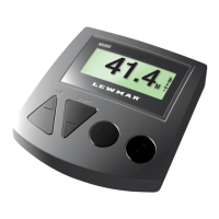
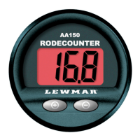
- Deck Switches:
- AIR Deck Switches: Ensure the small breather hole on the underside of the switch body remains clear of sealing compound.
- ELECTRIC Deck Switches: Use 16/0.2 wire to connect to the control box.
- Hydraulic Installation: Designed for use with Lewmar Commander power packs or similar. Plan hydraulic line routing (including case drain lines) from the supply to the windlass motor. Flush pipework to remove dirt/debris before final connection. Connect the case drain line. Position electric safety deck switch(es), remote control, and/or toggle switch in view of the windlass, anchor line, and bow roller. Connect switch wiring to the Commander system or proprietary system (minimum 3 amps, 12V or 24V DC supply).
- Operation (Hydraulic Models):
- Power Up/Down: Press the deck switch, remote control, or toggle switch (Anchor Up/Down). Ensure the brake band and gypsy pawl are released, and the dog drive is fully engaged.
- Manual Chain Release: Place a Lewmar winch handle in the brake band bi-square and secure the chain gypsy. Use another winch handle in the top nut to raise the capstan, disengaging the dog drive. Carefully release the brake to allow free-running chain, controlling descent by tightening/loosening the brake band.
- Capstan Operation (with rope only): Lock the gypsy with the brake band or pawl to prevent free-running chain. Place a Lewmar winch handle into the top nut and raise the capstan to disengage the dog drive. Press the Up button to power the Capstan.
- Dog Drive Engagement: Place a Lewmar winch handle into the top nut and lower the capstan onto the gypsy until resistance is felt, then backwind one quarter turn. Press the Up/Down switch for positive engagement. Tighten the top nut securely. Once engaged, stop power operation and release the brake band or gypsy pawl before continuing powered operation.
- Safety Warnings: Ensure the dog drive is fully engaged when powering in or out. Keep hands and feet clear of free-running chain. Do not leave a winch handle in the windlass while operating. Classification society rules require the chain to be held by a cable/chain stopper or strong point when at anchor to prevent windlass damage under storm conditions. It is recommended to use the vessel's engine to aid anchor recovery. Do not attempt to pull loads greater than the rated load of the windlass. When not in use, the anchor must be tied off onto a cleat or equivalent strong point.
Maintenance Features:
- Regular Checks: The windlass should be checked and cleaned every six months due to its harsh marine environment.
- Cleaning: Wash away salt deposits with fresh water.
- Lubrication: Clean and grease the main shaft, spline, and bearings using marine-grade grease.
- Brake Band: Remove the brake band assembly, clean the brake band and gypsy (do not allow grease onto the brake band surface). Check for wear and replace if necessary.
- Corrosion Check: Inspect the motor/gearbox for signs of corrosion. If corrosion is evident, clean and repaint with marine-grade oil-based enamel paint.