Starting-Up
17200138_002_C0 – (2016-10) –
Leybold
5
1 Starting-Up of the Slave
1.1 Power Supply Requirements
The ITR 200 SD has to be powered with two voltages:
1. 24 VDC, 18 W at the 15 pole Sub-D connector for the transmitter itself;
2. 24 VDC nominal, <2 W range (+11 … +25 V) at the DeviceNet micro style
connector for the DeviceNet transceiver.
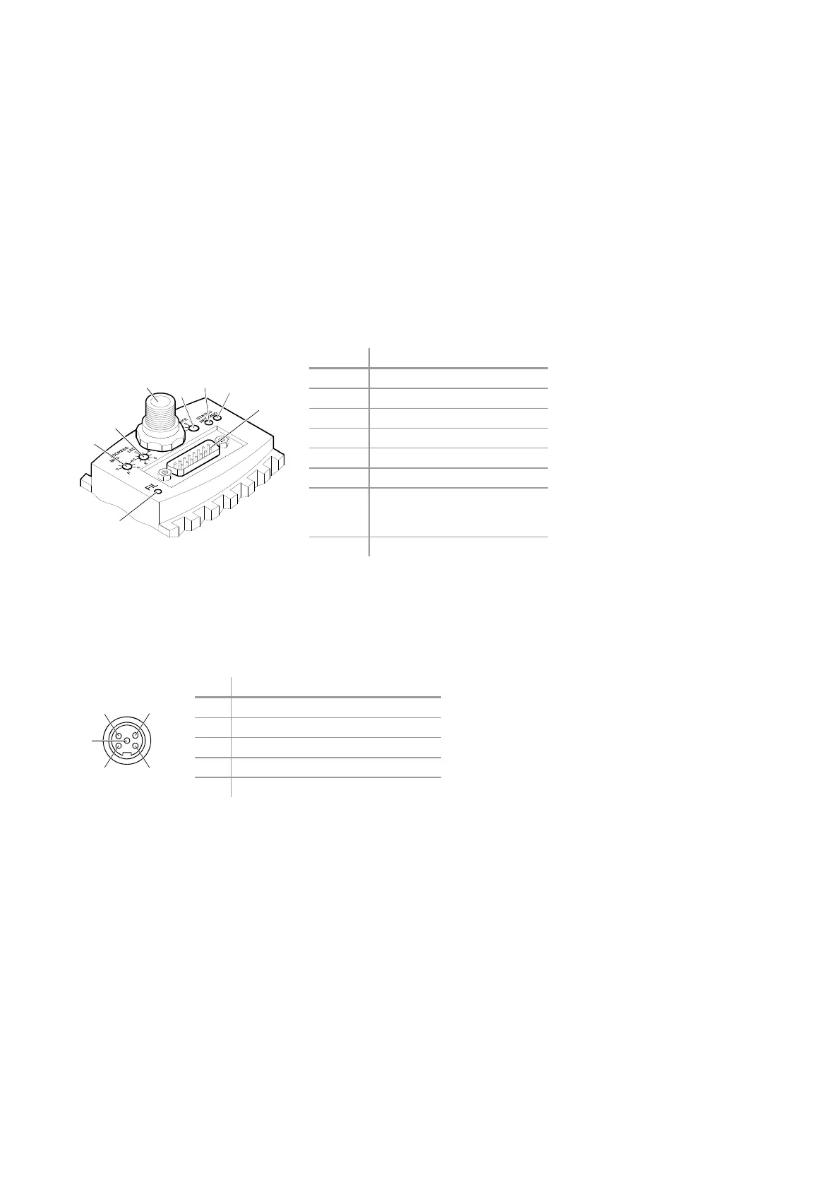
1.2 Front View of the ITR 200 SD
Position Function
1 Address switch ×10, decimal
2 Address switch ×1, decimal
3 DeviceNet connector
4 Data rate switch
5 Network status LED
6 Module status LED
7 "Sensor cable" connector
(Power, analog I/O, RS232C
I/O and Relay contacts)
8 Filament status LED
1.3 Connectors on the Device
The ITR 200 SD uses a "Sealed Micro-Style Connector" for the DeviceNet connec-
tion. The DeviceNet part of the transmitter is powered via the DeviceNet connector.
Pin Function
1 Drain
2 +24 V nominal (range 11 … 25 V)
3 V–
4 CAN_H
5 CAN_L
1
2
3
4
5
6
7
8
3
4
2
5
1
Pin Assignment of the Sealed
Micro-Style Connector