Starting-Up
6
17200138_002_C0 – (2016-10) –
Leybold
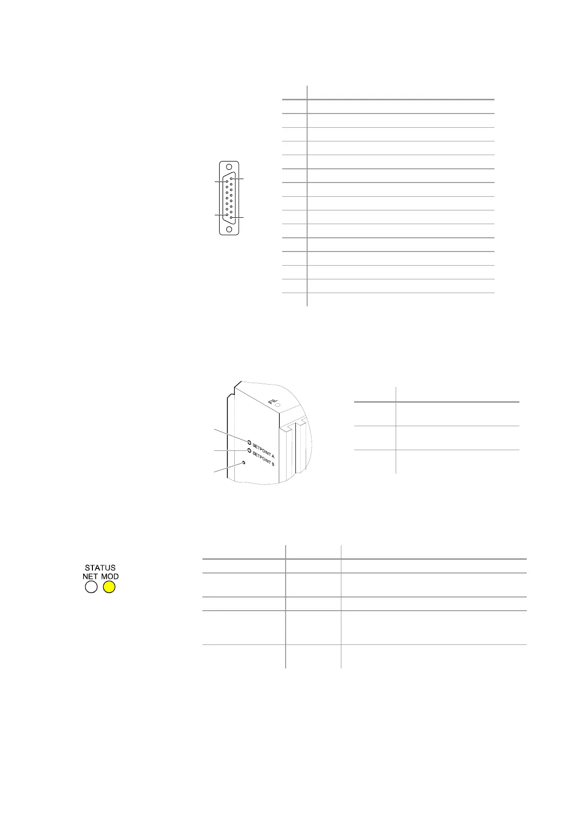
Pin Function
1 Setpoint A, relay common
2 Pressure output signal (0 … +10 V)
3 Threshold Setpoint A output (0 … +10 V)
4 Setpoint A, relay, n.o. contact
5 Supply sensor electronics common
6 Threshold Setpoint B output (0 … +10 V)
7 Degas input , high active
8 Supply sensor electronics +24 Volt
9 Setpoint B, relay common
10 Transmitter identification
11 Setpoint B, relay, n.o. contact
12 Signal common GND
13 RS232, TxD
14 RS232, RxD
15 do not connect
1.4 Side View of the ITR 200 SD
Position Function
9 Potentiometer for Setpoint A
threshold adjustment
10 Potentiometer for Setpoint B
threshold adjustment
11 Full Scale adjustment push
button
1.5 Indicators and Switches
Device state LED state Description
Power off dark No power applied to device.
Device self-test flashing
green-red
Device is in self-test.
Device operational green Device is operating normally.
Unrecoverable
fault
red Device has detected an unrecoverable fault.
As stated previously, all module level faults
are considered as unrecoverable faults.
Minor fault flashing red Device has detected a recoverable fault (e.g.
DeviceNet power supply not connected).
15
8
9
1
9
10
11
Pin Assignment of the 15-pin
D-Sub Connector
Module Status LED