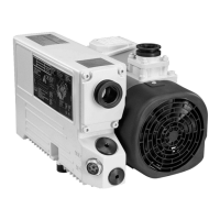
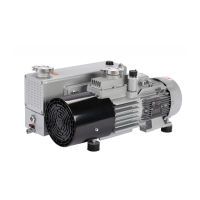
Principle of Operation
In the screw vacuum pumps of the SP 250 line the pump chamber is formed
by two synchronised displacing rotors and the housing.
A pair of tightly intermeshing right-handed and left-handed threads is used to
implement with only very few components a large number of stages and thus
very low ultimate pressures.
Figures 1.1 and 1.2 show how by the two rotors and the housing several
chambers are created which allow the gas to be compressed. Since the
rotors turn in opposing directions, the chambers “move” steadily from the
intake to the delivery side of the pump (fig. 1.2) so that the gas is conveyed
in a low-pulsation manner.
The continuous pumping action for the gas without the need of having to
deflect the gas will also allow pumping of particles entrained in the gas and
also vapours to a limited extent.
As in the case of other dry compressing (slot sealed) vacuum pumps, also in
the case of screw pumps very tight slots need to be maintained between the
components. Otherwise the leaks caused by the pressure drop would have a
negative effect on both pumping speed and attainable ultimate pressure.
Moreover, the pump might heat itself up too much due to unfavourable ther-
modynamic processes.
During operation the design of the SP 250 ensures that the slots are
maintained within the operational limits of the pump. In order to limit the tem-
peratures attained by the components, the housing of the pump chamber is
air-cooled. Also the rotors themselves are cooled: by oil which is pumped
through bores in the rotor shafts and which also lubricates the bearings and
the toothed wheels of the pump’s synchronising gear. Thus an even tempera-
ture spread is attained within the pump.
The amount of “inner compression” has a significant influence on the tem-
perature level within a vacuum pump. In the case of a foreline pump, most of
the work on compression is done while the gas is being ejected against the
delivery pressure, i.e. in the last stages of the pump. For this reason in the
case of the SP 250 the volume of the gas is already significantly reduced at
pressures which are as low as possible so as to minimise this work done on
compression. In this way the power requirement of the pump is reduced and
less heat needs to be dissipated.
Fig. 1.3 shows the pV diagram of screw pumps: (a) without inner compressi-
on, (b) with inner compression against the face side of the pump chamber
and (c) by reducing the chamber volume along the rotor. The surface areas
enclosed in the pV diagram are in each case proportional to the power
uptake of the pump. It is apparent that the most efficient method is to com-
press the gas which is to be pumped by reducing the axial pitch of the rotor
from the inlet to the delivery side (fig. 1.2) so that the chamber volume is
already reduced at low pressures (fig. 1.3c). In this way a power consumption
can be attained which is comparable to that of rotary vane pumps.
Gas compression
Slots
pV diagram