After having filled in the oil, the cover must be fitted once more.
The two cover sections are fitted in the reverse order. Here the EU-shaped
profile needs to engage in the chamfer of the bottom trough. This will ensure
that the cover halves are properly seated.
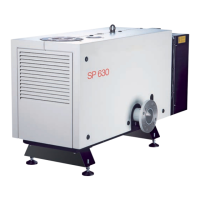
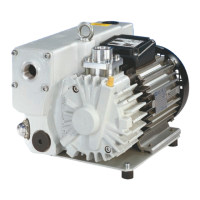
4.1.2 Switching the Pump On
The pump may only be switched on after it has been completely assem-
bled and with the fan’s housing closed.
Operation without intake line and discharge line or silencer is not allowed.
In the discharge line no pressure > pdis = pamb + 200 mbar must be
allowed to build up even if the discharged gases need to be collected or
contained.
Make sure that the gas flow at the discharge is not blocked or restricted in
any way.
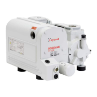
Depending on the pump version switch on
■
power supply for the SP-Guard
■
gas ballast
■
purge gas.
Then switch on the pump.
Start the pump only six times per hour at the most so as to avoid over-
loading the motor.
Between pumping chamber and gear, the pump has been equipped with
non-contacting seals. These seals have been provided with a vent at the side
of the pump. Small quantities of gear oil can escape from this vent. This will
in no way influence safe operation of the pump.
Please note safety information 0.4.7.
The gear housing is vented in the vicinity of fan wheel through two channels
on the side opposite the exhaust. By design, small amounts of gear oil may
escape through this vent. This will not adversely affect operation of the pump.
CAUTION
NOTICE