2 Transport and Storing
Please note safety information 0.1.5 and 0.1.6.
Before transporting the pump always drain the gear oil out.
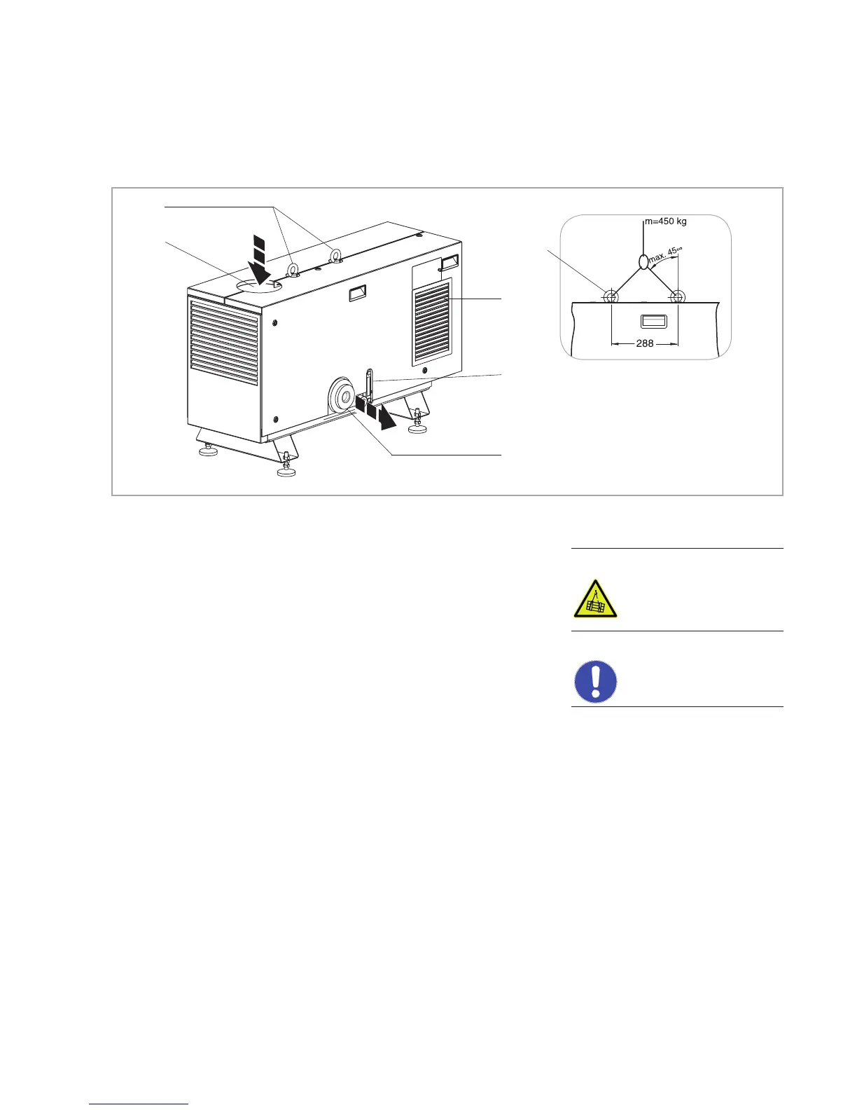
Located on the top side are as standard 2 crane eyes, in accordance with
DIN 582-M16-C15N. Only these ring nuts may be used when lifting the
pump with a crane. When using ropes to lift the pump at the ring nuts,
please observe the maximum permissible angles as given in fig. 2.1
Transporting of pump combinations (like screw pump & RUVAC, for example)
is not permitted, the ring nuts are not rated for such loads!
The ring nuts have been secured and must not be loosened.
When transporting the pump with fork lifters or alike, the pump must be
secured on the supplied pallet or a suitable other pallet.
The frame of the pump has not been designed for use with fork lifters or alike
since there is the risk that the pump may topple when accelerating or moving
up ramps.
However, the pump’s frame is rugged enough for attaching lifting means for
the purpose of installing or positioning the pump within a system. When
doing so note the risk of slipping and toppling.
If required secure the pump. For transporting, the silencer must be disassem-
bled as otherwise there is the risk of toppling.
CAUTION
NOTICE
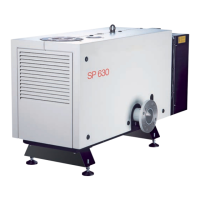
1 Intake port
2 Crane eye (ring nuts)
3 Oil sight glass
4 Exhaust
5 Fan grille
Arrows = Direction of pumping
action
Fig. 2.1 Transport and connection components as well as inspection locations on the SP 250
2
3
4
5
1
Lifting with crane and a rope
2