4.2.3 Purge Gas Operation
(only for certain pump versions, see Section 1.4)
In order to ensure full protection by the purge gas, the inlet pressure of the
purge gas into the pressure reducer must be within the range of 3 to 10 bar.
At the pressure reducer, a system pressure of 2.5 bar needs to be set up . At
this setting there results a purge gas flow of approximately 20 Std. l/min.
Always switch on the purge gas first and then the pump.
After having switched off the pump, the seals should be purged at least for
one further hour with purge gas. Depending on the type of process gas
which was pumped, an even longer purging time may be required.
During the purging time, the blocking facilities installed in the exhaust line
must be open, as otherwise and unacceptably high pressure might build
up within the pump.
At the maximum permissible pressure difference between the exhaust of the
pump and atmosphere of +200 mbar, a maximum purge gas flow of 8 Std. l/
min may escape into the environment.
When using nitrogen as the purging gas, ensure sufficient ventilation of the
location where the pump is installed.
Operation with purge gas does in no way influence the pumping speed of the
pump.
The purge gas flow is continuously monitored while the SP Guard is supplied
with voltage. Therefore the SP Guard displays an error message when the
pump is at a standstill and there is no gas flow. Thus we recommend the fol-
lowing power-off sequence: pump, SP Guard, purge gas. Switch on the
pump in reverse order.
An error message will be displayed (and must be acknowledged), if the purge
gas will be turned off prior to the SP Guard or turned on after the SP Guard.
VORSICHT
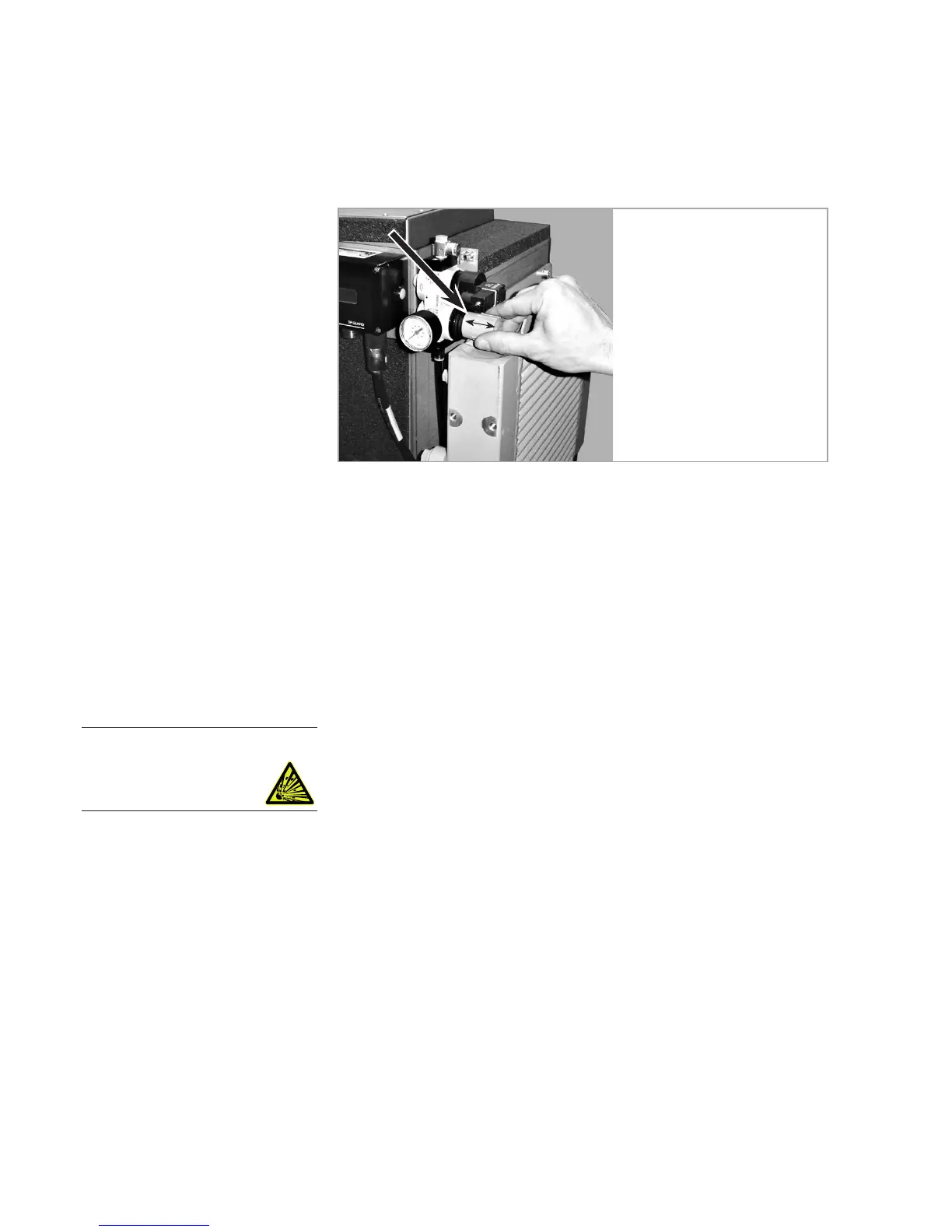
Fig. 4.4 Adjust the pressure reducer
To adjust, pull the blue adjust-
ment knob to the right, set to 2.5
bar, and for the purpose of secur-
ing the adjustment knob, push it
to the left and arrest it.