3.4.2 Star/Delta Start-up Circuit
In the case of this circuit (star circuit) a lower voltage is applied to the motor
coils upon switching on, resulting in a lower switch-on current.
During this phase also power and torque of the motor are lower.
In order to attain the operating levels for torque and power rapidly, the start-
up phase should be as short as possible, approximately 4 to 5 seconds.
Thereafter the switchover to continuous operation (delta circuit) should occur.
Here also a motor protection switch for heavy run-up (class 20) should be
used.
3.4.3 Soft Start
In order to reduce the current taken up from the mains supply, the supply
voltage to the motor may be electronically controlled during the start-up time.
Within the starting time, the motor must reliably reach its nominal values. The
adjustable starting voltage should be 60% of the nominal voltage. The ramp
time should be 15 seconds.
The highest switch on currents (140 A/400 V) must be taken account when
selecting the soft starting unit (Siemens 3RW30, for example). In addition,
note the installation instructions of the soft starter manufacturer.
3.4.4 Mains Connection
The mains power needs to be supplied via an external mains switch with ON/
OFF key by the customer.
The mains connection needs to be provided in accordance with the type of
motor protection. The mains supply must match the mains power rating of
the motor.
The line cross-section for the mains power supply needs to be calculated in
consideration of the cable length and the available mains circuit breaker.
Using a mains power supply line having a cross-section of at least 4 x 6 mm
2
is recommended.
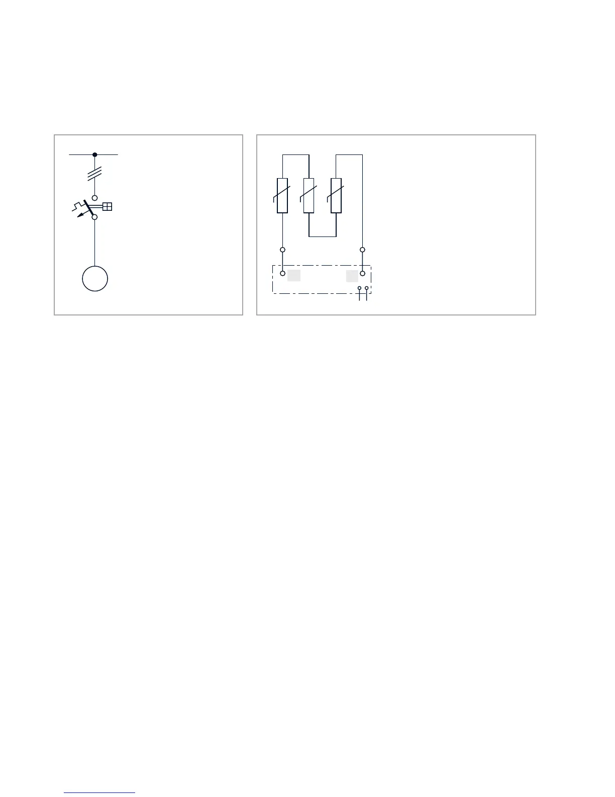
Fig. 3.2 Example for PTC temperature sensor circuit
Protection arrangement
PTC temperature sensor with controller
Protection against:
- Overload during cont. operation
- Long starting up and stopping
processes
- High switching frequency
in the case of faults against:
- Obstructed cooling
- Increased temperature of the coolant
- Single-phase operation
- Frequency fluctuations
- Switching to a seized rotor
10
11
+
+
+
2.5 V max.
Fig. 3.1 Examples of motor protection circuits
Protection arrangement
Motor protection switch with
thermal and solenoid overcur-
rent release (class 20).
Protection against:
Overload during continuous
operation
Seized rotor
M
3 ~