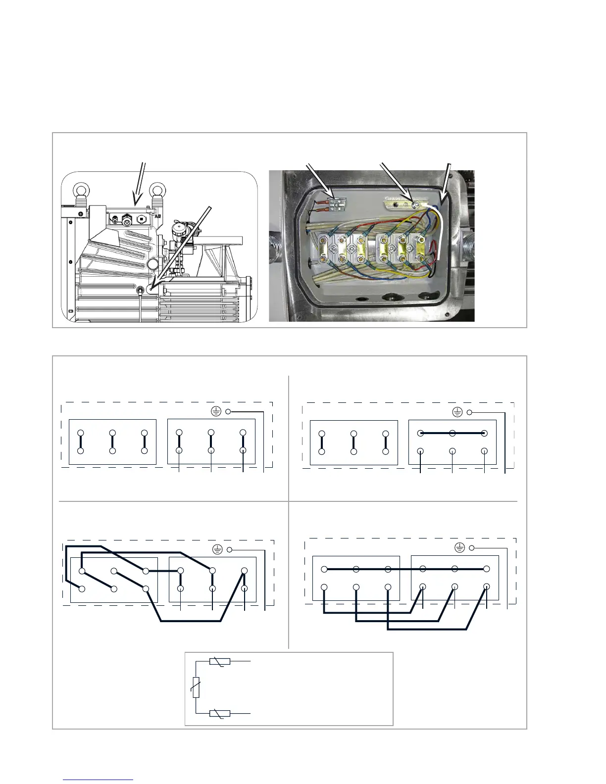
Fig. 3.3 Electrical connections in the junction box, the wires are protected by additional silicone sleeves
Junction box
Temperature sensor
PE connection
Lay the PE wire within the
junction box as shown!
Potential equalisa-
tion connection
Fig. 3.4 Mains connection (connection diagrams in the junction box)
- Delta circuit
3~ / 400 V 50 Hz
3~ / 460 V 60 Hz
Δ
Y - Star circuit
U
2
V
2
W
2
U
5
V
5
.W
5
PE
L
1
L
2
L
3
W
6
U
6
V
6
U
1
V
1
W
1
U
2
V
2
W
2
U
5
V
5
.W
5
W
6
U
6
V
6
U
1
V
1
W
1
For starting only!
PE
L
1
L
2
L
3
For continuous operation!
3~ / 400 V 50 Hz
3~ / 460 V 60 Hz
U
2
V
2
W
2
U
5
V
5
.W
5
PE
L
1
L
2
L
3
W
6
U
6
V
6
U
1
V
1
W
1
U
2
V
2
W
2
U
5
V
5
.W
5
PE
L
1
L
2
L
3
W
6
U
6
V
6
U
1
V
1
W
1
For starting only!
For continuous operation!
- Double Delta circuit U/2
3~ / 200 V 50 Hz
3~ / 210 V 60 Hz
ΔΔ
YY - Double Star circuit U/2
3~ / 200 V 50 Hz
3~ / 210 V 60 Hz
Three-phase motor voltage selectable,1:2