14
GA 01.600/10.02 - 07/01
Operation
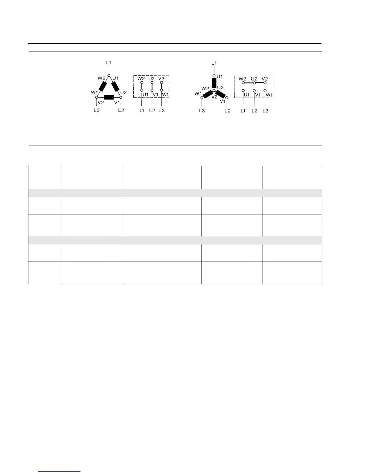
Fig. 5 Wiring diagram for the TRIVAC E pumps with three-phase motor
Delta circuit Star circuit
Voltage ranges for Max. current consumption Min. current Setting for the
the three-phase at an intake pressure of consumption at motor protection
motors about 300 mbar ultimate pressure switch (motor data)
D 50 Hz 200 V - 240 V 2.2 A - 2.6 A 1.6 A - 2.5 A 2.8 A
60 Hz 200 V - 266 V 2.5 A - 2.3 A 1.4 A - 1.9 A 2.8 A
Y 50 Hz 346 V - 415 V 1.2 A - 1.5 A 0.9 A - 1.4 A 1.6 A
60 Hz 346 V - 460 V 1.4 A - 1.35 A 0.8 A - 1.2 A 1.6 A
D 50 Hz 200 V - 240 V 3 A - 3.8 A 2 A - 3.3 A 4 A
60 Hz 200 V - 277 V 3.3 A - 3.5 A 1.8 A - 3.1 A 3.6 A
Y 50 Hz 346 V - 415 V 1.8 A - 2.1 A 1 A - 1.5 A 2.3 A
60 Hz 346 V - 480 V 1.95 A - 2 A 0.95 A - 1.45 A 2.1 A
TRIVAC D 5 / 10 E
TRIVAC D 16 E
2.3.2.1 Current Drawn by the Three-Phase Motors of the TRIVAC D 5 E - D 16 E