Operation
13
GA 01.600/10.02 - 07/01
2.3 Electrical Connection
During all electrical work ensure that the
power supply lines have reliably been swit-
ched off and protected against being swit-
ched on inadvertently.
In order to prevent the pump from running
up unexpectedly after a power failure, the
pump must be connected to the system
controller in such a way that the pump may
only be re-started manually. This applies
equally after the pump has been switched
off through an emergency switch.
The electrical connections may only be
made by an electrician as defined by VDE
0105 in accordance with the VDE 0100 gui-
delines.
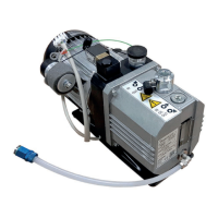
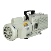
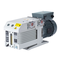
The pumps are supplied with either an AC motor or a
three-phase motor.
2.3.1 Pumps with AC Motor
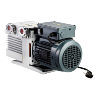
The pump may be directly connected via its mains cable
and its plug to the mains.
In the case of 230 V mains, 6 A slow blow or 10 A fast
blow fusing is required as a minimum.
A check on the direction of rotation is not required since
this is fixed.
The thermal motor overload protector protects the motor
in case it is overloaded.
The mains voltage must comply with the voltage stated
on the name plate.
When the thermal motor overload protec-
tion system has switched the motor off, the
motor will automatically cut in again when
the temperature has dropped below the
maximum permissible operating tempera-
ture.
2.3.2 Pumps with Three-Phase Motor
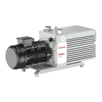
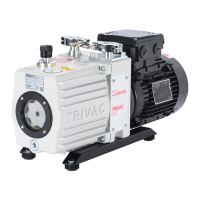
The TRIVAC E pumps equipped with a three-phase
motor are delivered without the components required for
their electrical connection.
You must connect the pump using an appropriately rated
cable (we recommend: AWG 18 for the 5 to 10 type
models and AWG 16 for the 16 type modes) and a sui-
tably rated motor protection switch. The value set on the
motor protection switch must correspond to the current
rating stated on the name plate of the motor.
Shown in Fig. 5 is the way in which the pump having a
three-phase motor (50/60 Hz) may be connected in Star
or Delta fashion. Please also take note of the information
given on the name plate of the motor.
After having connected the motor and each
time after having made a change to the
wiring you must check the direction of rota-
tion.
For this switch the motor on briefly and
determine whether or not a suitable plate (a
blank flange, for example) held in front of
the intake is sucked towards the pump’s
body. If this is not the case you must inter-
change two of the mains phases.
Note the direction indicating arrow on the
fan cowl.
Caution
Warning
Warning
 Loading...
