5 Installation
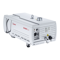
Figure 3.
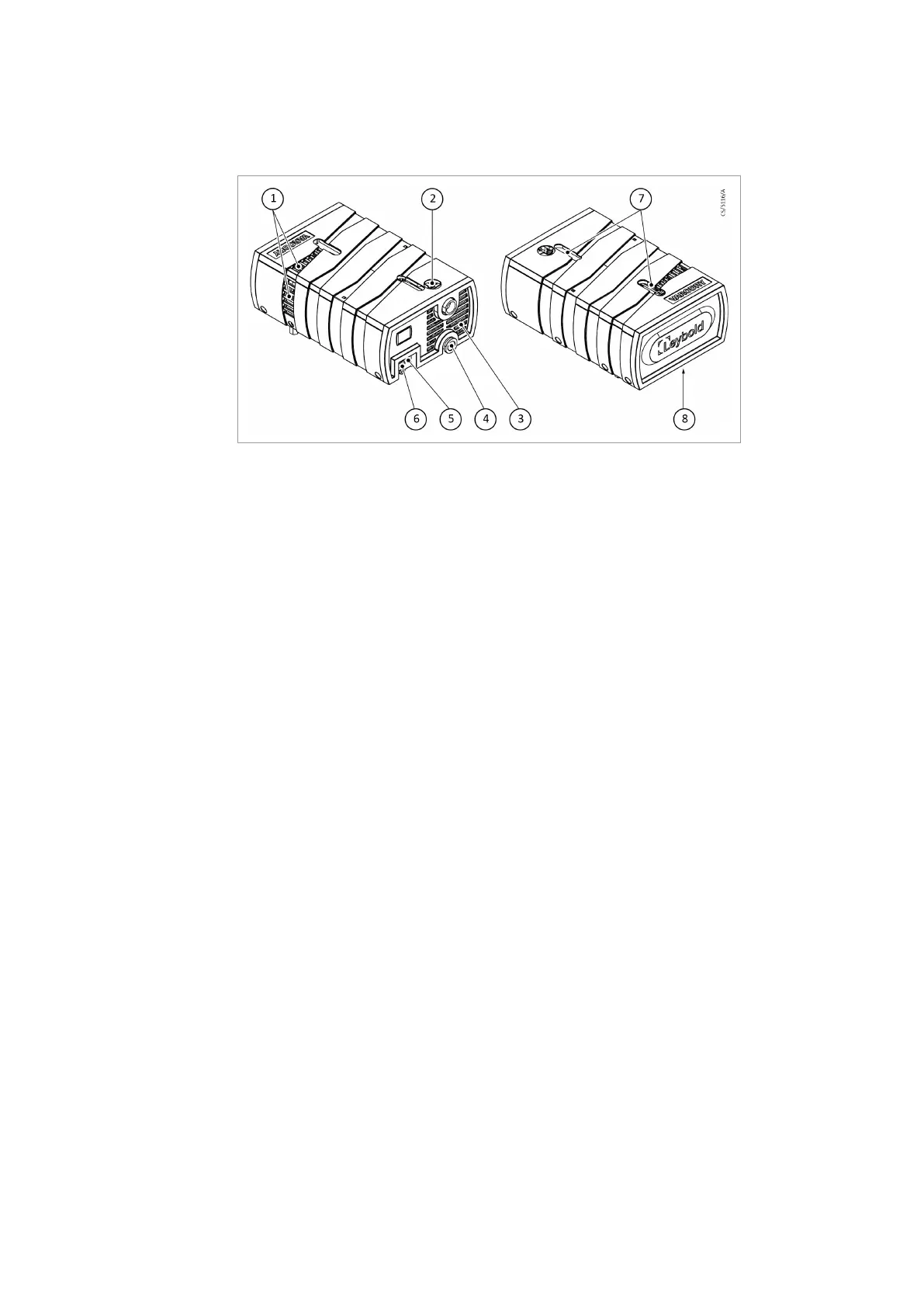
Connections and controls
1.
Cooling air - out
2.
Inlet ange
3.
Cooling air - out
4.
Exhaust ange
5.
Purge gas port (optional)
6.
Electrical feedthroughs
7.
Lifting eye
8.
Cooling air - in
1.
Cooling air - out
2.
Inlet ange
3.
Cooling air - out
4.
Exhaust ange
5.
Purge gas port (optional)
6.
Electrical feedthroughs
7.
Lifting eye
8.
Cooling air - in
5.1 Placement
The cooling air intake and outlets must not have a blockage to prevent insufcient cooling
of the pump. Figure: Connections and controls on page 13.
5.2 Conforming Use
The VARODRY range is designed for use in light and medium industrial applications. The
pumps are capable to handle small amounts of dust and liquids however the use of inlet
lters or liquid traps is recommended in such cases. They are not hermetically sealed and
will release small amounts of pumped gases to ambient even if the exhaust port is
connected to an exhaust pipework. They are suitable for pumping water steam or other
vapors within the limits of the vapor tolerance. The pump can be used both continuously
at a suction pressure range of 0.01 mbar to 1050 mbar as well as for cyclic pump
operations within this pressure range.
5.2.1 Non-conforming Use
The VARODRY is not suited for pumping of:
▪ Radioactive substances
▪ Explosive substances
▪ Ignitable gas mixtures
▪ Pyrophoric gases
▪ Liquids
▪ Media in signicant amounts condensing in the pump (Except from water)
▪ Solids
▪ Corrosive gases
▪ Oxidative substances with the exception of £ 21% oxygen in the air
▪ Toxic gases
13
300766038_002 - © Leybold
Installation