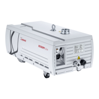
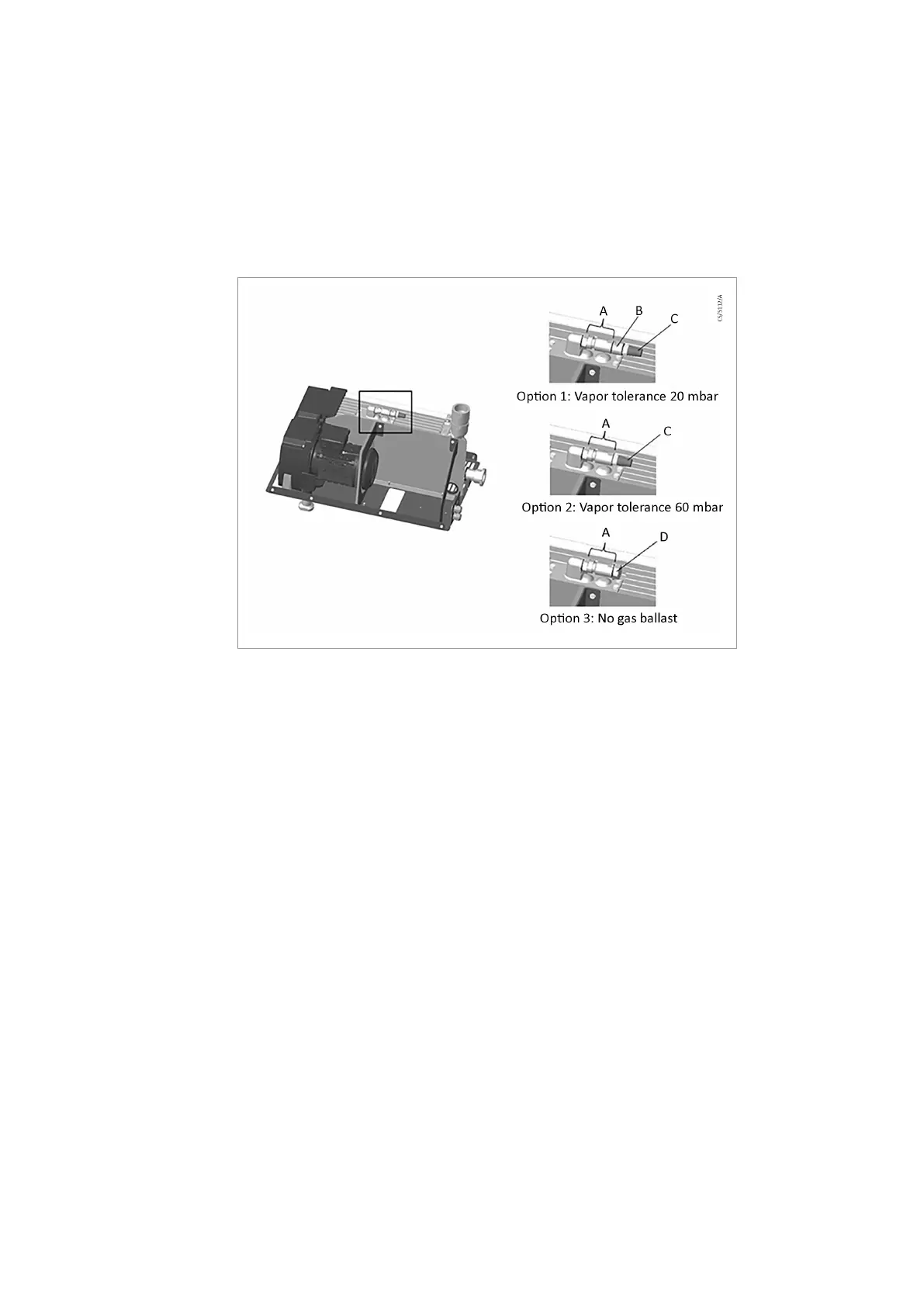
5.8 Manual Gas Ballast Conguration
The VARODRY with manual gas ballast (standard version) is delivered with components
that can be mounted to the pump body in order to achieve different water vapor
tolerances. The following pictures show the possible setups.
When changing the setup, make sure that the gaskets are in good condition and that the
parts are tightened properly.
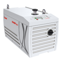
Figure 7. Manual gas ballast conguration
A.
Nozzle 60 mbar water vapor tolerance
B.
Nozzle 20 mbar water vapor tolerance
C.
Silencer/Filter
D.
Plug (no gas ballast)
A.
Nozzle 60 mbar water vapor tolerance
B.
Nozzle 20 mbar water vapor tolerance
C.
Silencer/Filter
D.
Plug (no gas ballast)
5.9 Connecting solenoid gas ballast/purge valves
The VARODRY with solenoid valves (optional) has three separate valves as shown in
Figure: Connecting solenoid gas ballast/purge valves on page 18.
Connect 24 V DC (!) supply voltage to the solenoid valves that will be used in the
application. The valves can be activated independently depending on the application
requirements.
17
300766038_002 - © Leybold
Installation