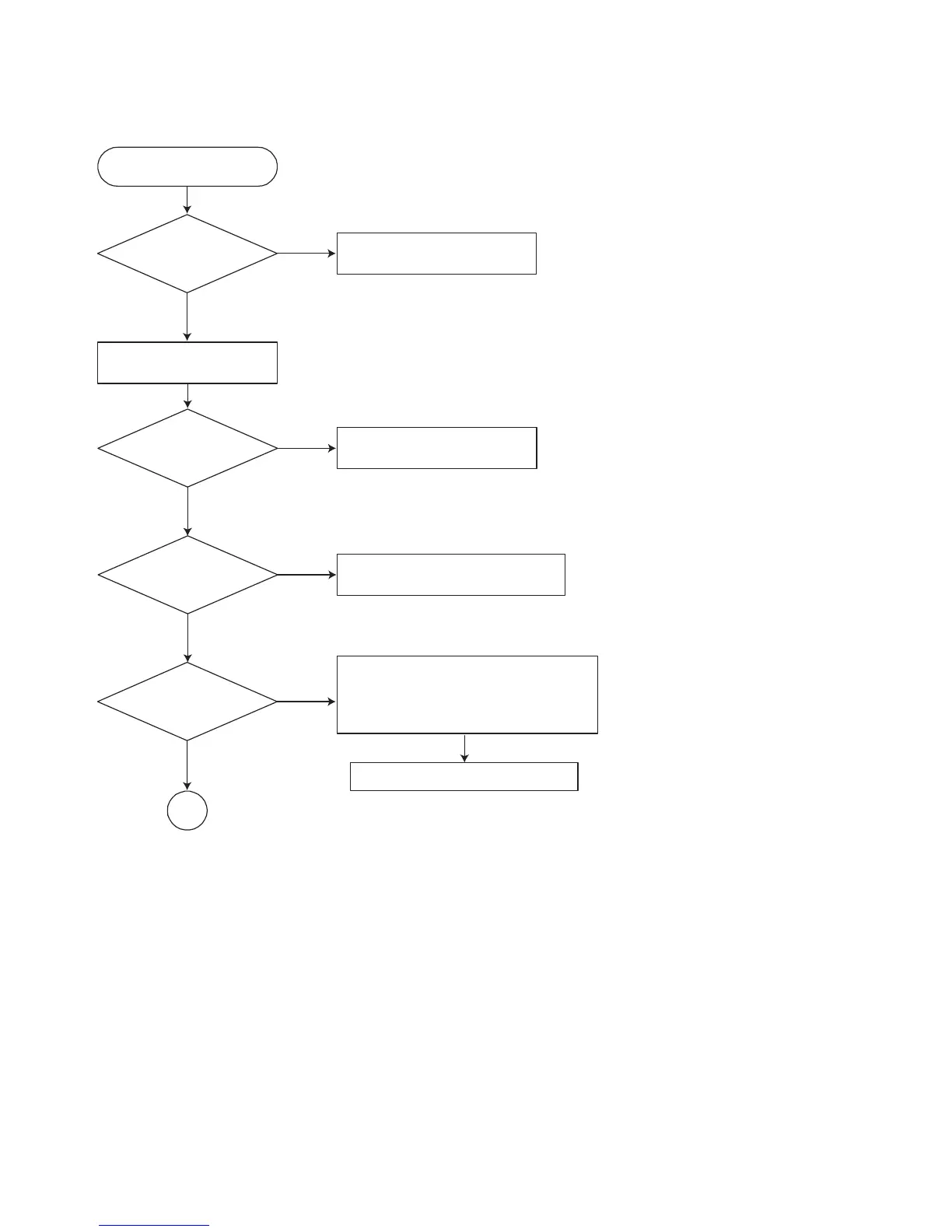
EasyManuals Logo

LG ACC55R User Manual

LG ACC55R
83 pages
To Next Page IconTo Next Page
To Previous Page IconTo Previous Page
Page #25 background imageLoading...
Page #25 background image
3-2
2. Test & debug flow
TEST
Check the POWER PART
No
Yes
No
Yes
No
No
Yes
Yes
Check the POWER PART
Check the regulators or diode.
1. Check 27MHz system clock.
2. Check systemreset circuit.
3. Check FLASH R/Wenable signal PRD,
RWR.
4. Check FLASH Memory related circuit.
Check the
AC Vol tage
Power PCBA (110V
or 220V)
Switch on the Power PCBA
Is the
DC Voltage
outputs OK? (-44V, -22V,
-26.5V, ±12V, 5.6V, 3.3V,
5V, 7V, 8V)
Are 3.3V and 5V DC
outputs normal on main
PCBA?
Update
FLASH
successfully?
Replace FLASH
A

Questions and Answers:

Question and Answer IconNeed help?

Do you have a question about the LG ACC55R and is the answer not in the manual?

LG ACC55R Specifications

General IconGeneral
BrandLG
ModelACC55R
CategoryReceiver
LanguageEnglish

Related product manuals