55
Installation Manual
Due to our policy of continuous product innovation, some specifications may change without notification.
©LG Electronics U.S.A., Inc., Englewood Cliffs, NJ. All rights reserved. “LG” is a registered trademark of LG Corp.
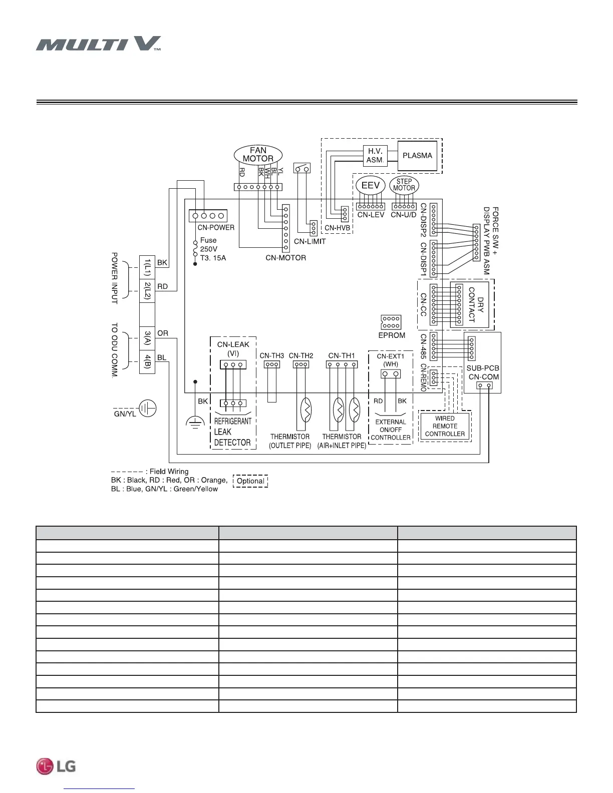
Table 14: Standard (Gen 4) Wall-Mounted SBL, SCL Chassis Wiring Diagram Legend
WIRING
Standard Wall-Mounted SBL, SCL Chassis
Figure 58: Standard (Gen 4) Wall-Mounted SBL, SCL Chassis Wiring Diagram
)LOWHUDFFHVVRULHVDUHDYDLODEOHVHSDUDWHO\$OZD\VIROORZDOOORFDOVWDWHDQGQDWLRQDOEXLOGLQJFRGHVZLWKWKHXVHRIDQ\SURGXFW
7RHQDEOH*HQHUDWLRQIHDWXUHVRXWGRRUXQLW',3VZLWFKQRPXVWEHVHWWR213OHDVHUHIHUWRWKH0XOWL9,90XOWL9:DWHU,90XOWL96
Engineering Manual for additional information.
PCB Connection Purpose Function
CN-POWER AC Power supply AC Power line input for indoor controller
CN-MOTOR Fan motor output Motor output of BLDC
CN-HVB* Air cleaner* Air cleaner control*
CN-LEV EEV output EEV control output
CN-U/D Step motor Step motor output
CN-DISP2 Display Display of indoor status
CN-DISP1 Display Display of indoor status
CN-CC Dry contact Dry contact line
CN-485 Communication Connection between indoor and outdoor units
CN-REMO Remote controller Remote control line
CN-EXT1 External ON / OFF controller External ON / OFF controller connection
CN-TH1 Return air and inlet pipe thermistor Return air and inlet pipe thermistor connection
CN-TH2 Outlet pipe thermistor Outlet pipe thermistor connection
CN-TH3 Float switch Float switch connection
 Loading...