Do you have a question about the LG FB163U and is the answer not in the manual?
Handling precautions for the pick-up and CD player repairs, focusing on static electricity.
Techniques to prevent static electricity damage to sensitive components during servicing.
Detailed technical specifications including power, tuner, amplifier, and player capabilities.
Exploded view of the main chassis and frame components.
Exploded view of the CD/DVD deck mechanism and its parts.
Exploded view of the front speaker assembly and its components.
Pin configurations and block diagrams for key integrated circuits.
Flowcharts for diagnosing and resolving electrical issues in various parts.
Oscilloscope waveform examples for critical signals and operational states.
Diagrams illustrating electrical connections, system architecture, and component interactions.
Detailed electrical schematics and printed circuit board layouts for the device.
| RMS rated power | 160 W |
|---|---|
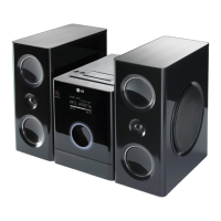
| Type | Home audio micro system |
| Cassette deck | No |
| Product color | Black |
| Number of decks | 1 deck(s) |
| Optical disc player | Yes |
| Volume control | Rotary |
| Headphone connectivity | 3.5 mm |
| USB 2.0 ports quantity | 1 |
| Dimensions (WxDxH) | 175 x 269 x 290 mm |
| Power requirements | AC 100 - 240 V 50/60 Hz |
| Media types supported | mp3, wav, wma |
| Power consumption (typical) | 60 W |
| Storage temperature (T-T) | -5 - 55 °C |
| Operating temperature (T-T) | 0 - 40 °C |
| Operating relative humidity (H-H) | 5 - 85 % |
| Weight | 3200 g |
|---|