Do you have a question about the LG L1718S-BN - - 17" LCD Monitor and is the answer not in the manual?
Details about the LCD panel's physical properties, size, pitch, and color depth.
Specifies viewing angles, luminance, contrast ratios, and panel types.
Defines video input signal types, sync signal configurations, and impedance.
States the maximum display resolution supported by the monitor.
Outlines power input requirements and consumption levels for various modes.
Lists operating temperature, humidity, MTBF, and lamp life specifications.
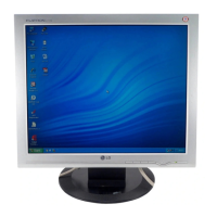
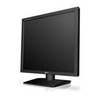
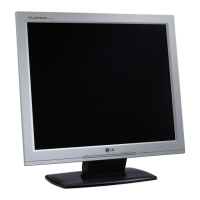
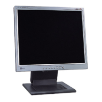
Provides the physical dimensions of the monitor with its stand.
Specifies the monitor's net and gross weight with tilt/swivel adjustments.
Highlights critical safety components and guidelines for their replacement.
Instructions for safely handling the LCD module and backlight unit to prevent damage.
Warnings and procedures to avoid electric shock during servicing operations.
Brief cautions regarding tool usage and service environment to prevent hazards.
Guidelines for safe and proper servicing procedures and general precautions.
Procedures for preventing damage to sensitive electronic components from static electricity.
Best practices for soldering and unsoldering electronic components and circuit boards.
Steps for replacing common components like ICs, transistors, diodes, and resistors.
Methods for repairing damaged copper traces and foil patterns on circuit boards.
Steps for safely detaching the monitor stand base from the unit.
Procedure for removing the monitor neck assembly.
Instructions to remove the hinge cover for access.
Steps for detaching the hinge assembly from the monitor.
Guide for separating the front bezel from the monitor casing.
Explains the function of the video signal processing circuitry.
Details the power supply regulation and distribution within the monitor.
Describes the microcontroller's role in control and data storage.
Instructions for configuring the serial port for monitor adjustments.
Procedures for reading and writing Extended Display Identification Data.
Diagnostic steps for when the monitor does not power on.
Troubleshooting steps for backlight illumination issues.
Procedures for diagnosing unstable DC power outputs.
Steps to resolve issues with unstable output power levels.
Diagnosing issues causing a black screen with backlight on.
Troubleshooting guide for displays showing a white screen.
Steps to diagnose and fix general screen display problems.
List of part numbers for the INL model variant.
List of part numbers for the CPT model variant.
Circuit diagram for the DC-to-DC power conversion stage.
Diagram illustrating how input signals are handled by the monitor.
Schematics for the scaler and associated control microcontrollers.
Diagrams for the keypad input and LED indicator circuits.
Schematics for the inverter and main power supply sections.