


D
Devin JohnsonSep 5, 2025
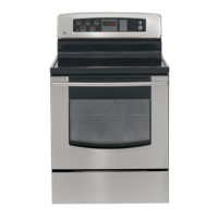
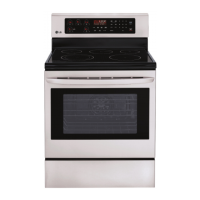
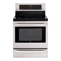
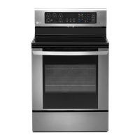
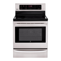
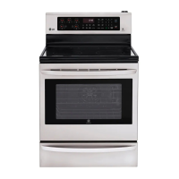
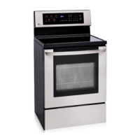
What to do if the oven racks fit too tight in my LG LRE30453ST Ranges?
- Bbradley92Sep 5, 2025
If the oven racks fit too tight in your LG Ranges, it might be because the racks were cleaned in a self-clean cycle. Apply a small amount of vegetable oil to a paper towel and wipe the edges of the oven racks with the paper towel. Do not spray with Pam or other lubricant sprays.